
Wireless Audio Signal Generator using CS4334 and ESP32
Background
According to Wikipedia,
“A signal generator is one of a class of electronic devices that generates electronic signals with set properties of amplitude, frequency, and wave shape. These generated signals are used as a stimulus for electronic measurements, typically used in designing, testing, troubleshooting, and repairing electronic or electroacoustic devices, though it often has artistic uses as well. There are many different types of signal generators with different purposes and applications and at varying levels of expense.”
An audio signal generator is a type used to generate signals in the range of human hearing (1Hz - 22kHz) and is useful for designing and testing audio amplifier circuits. This is the type we’ll be building as all prerequisites are readily available. Despite the restriction on bandwidth (output frequency range), it is still quite versatile as a piece of HomeLab equipment.
I found particular necessity for a signal generator when building power circuits which require precise inductor values which cannot be conveniently measured e.g using a multimeter.
Capacitor values as well may be measured using a signal generator and oscilloscope
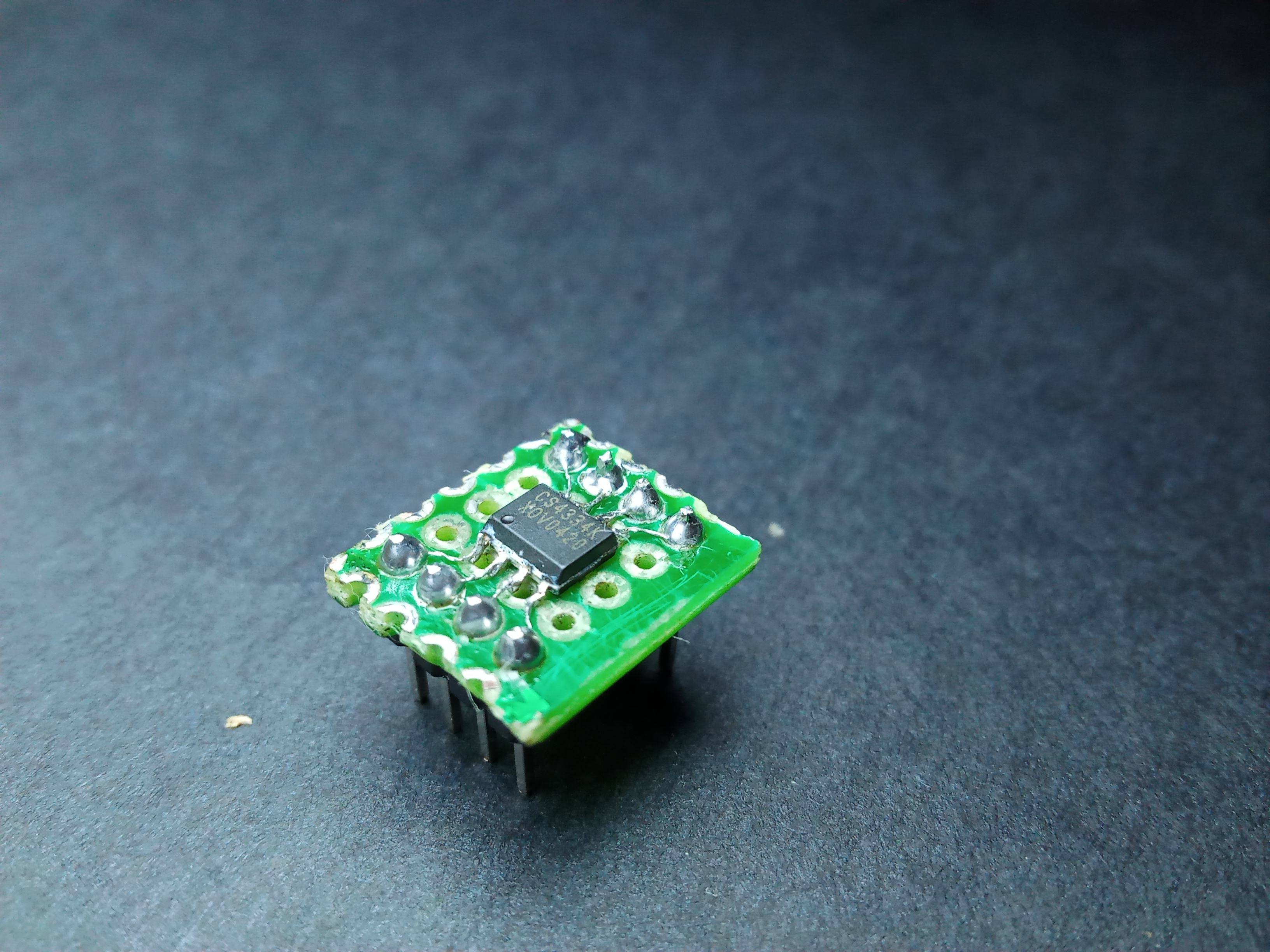
Object of ReFab : CS4334
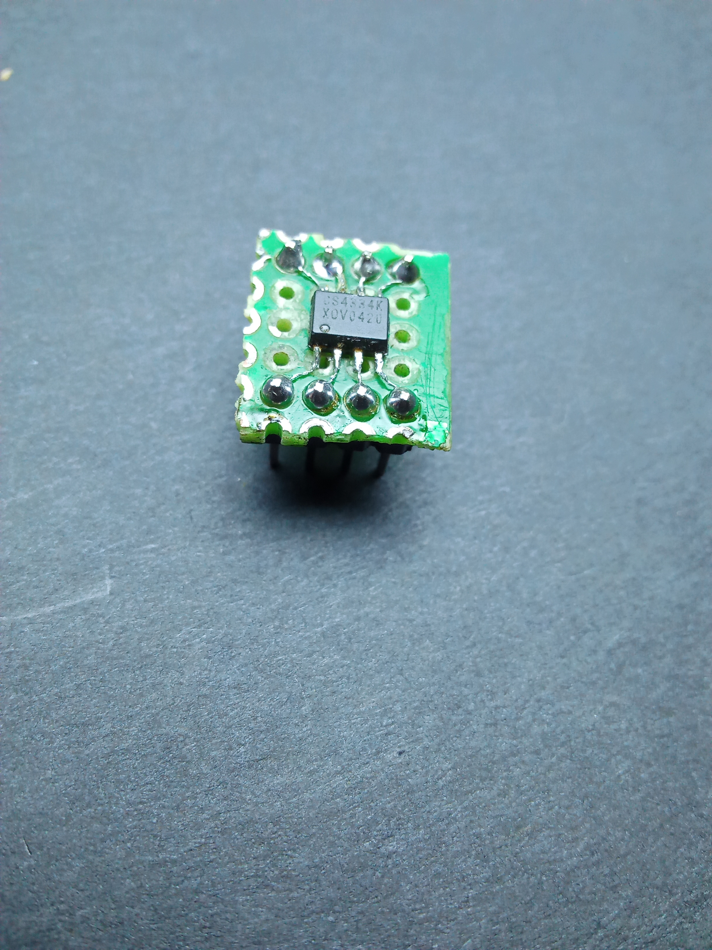
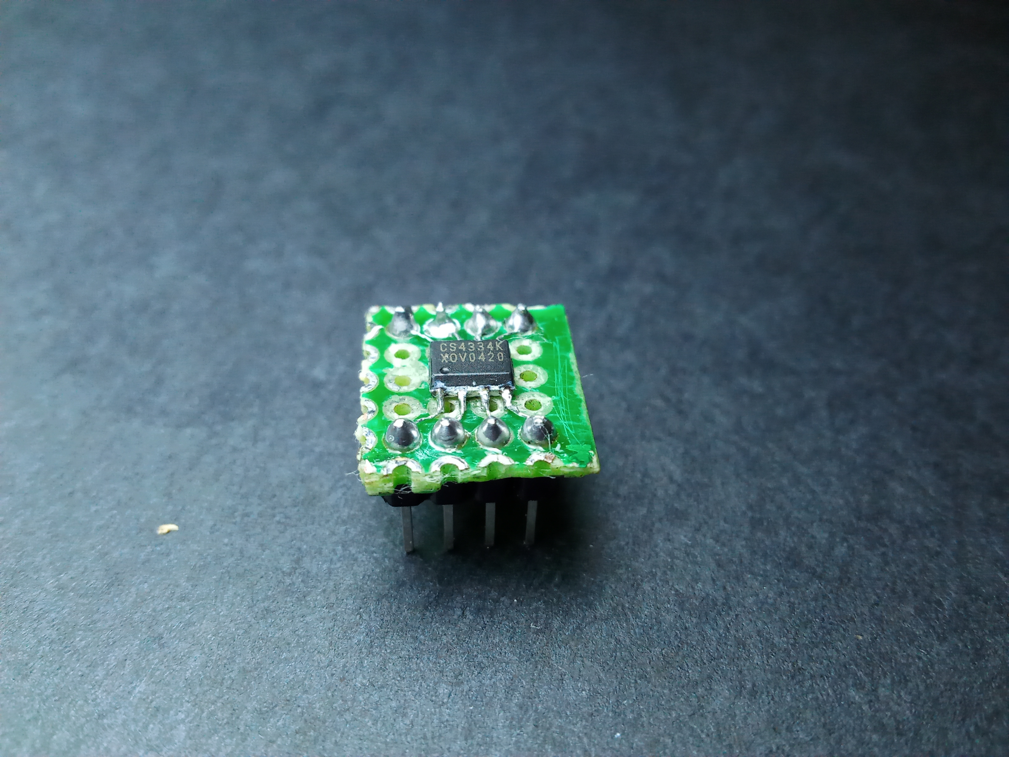
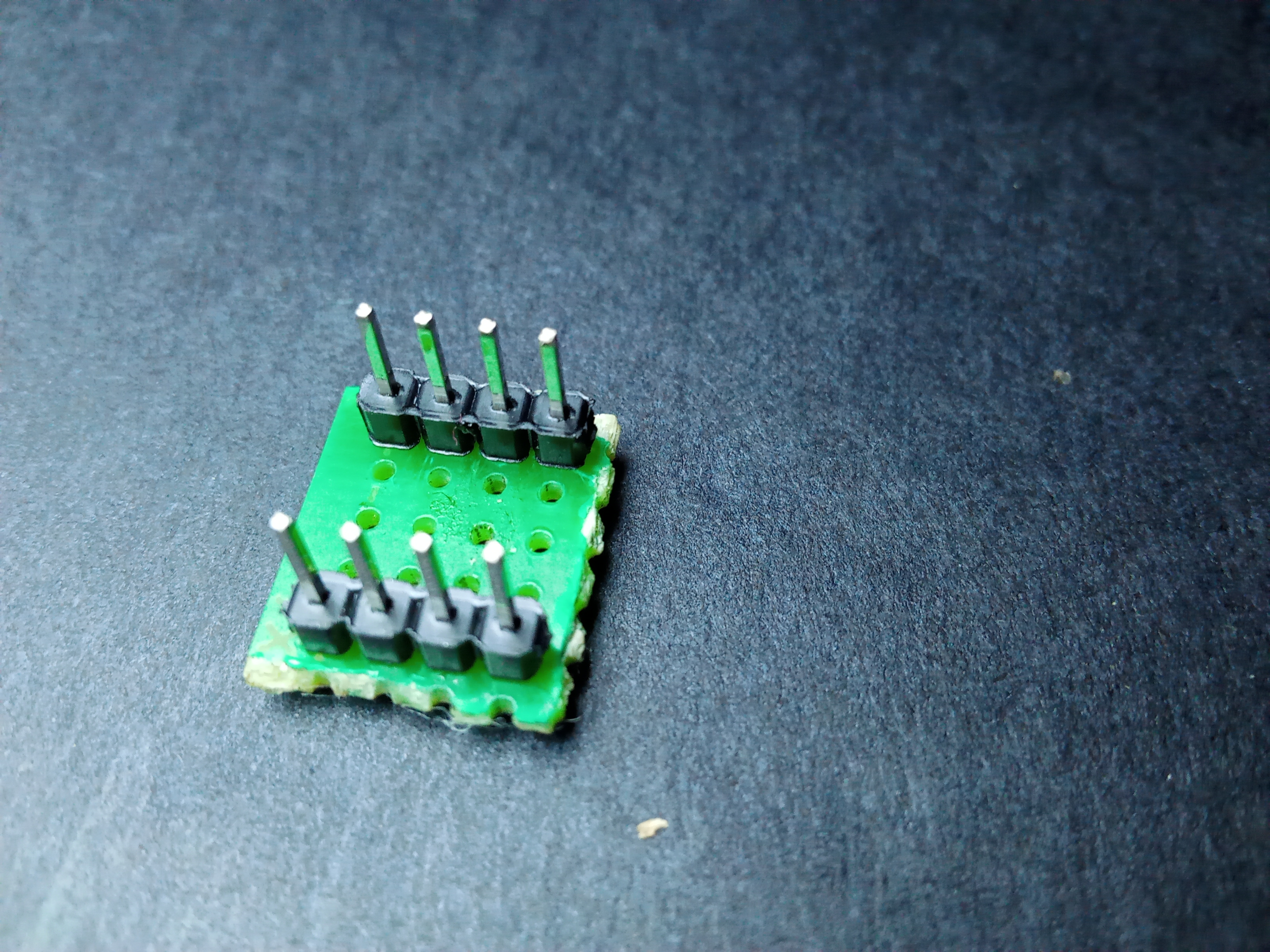
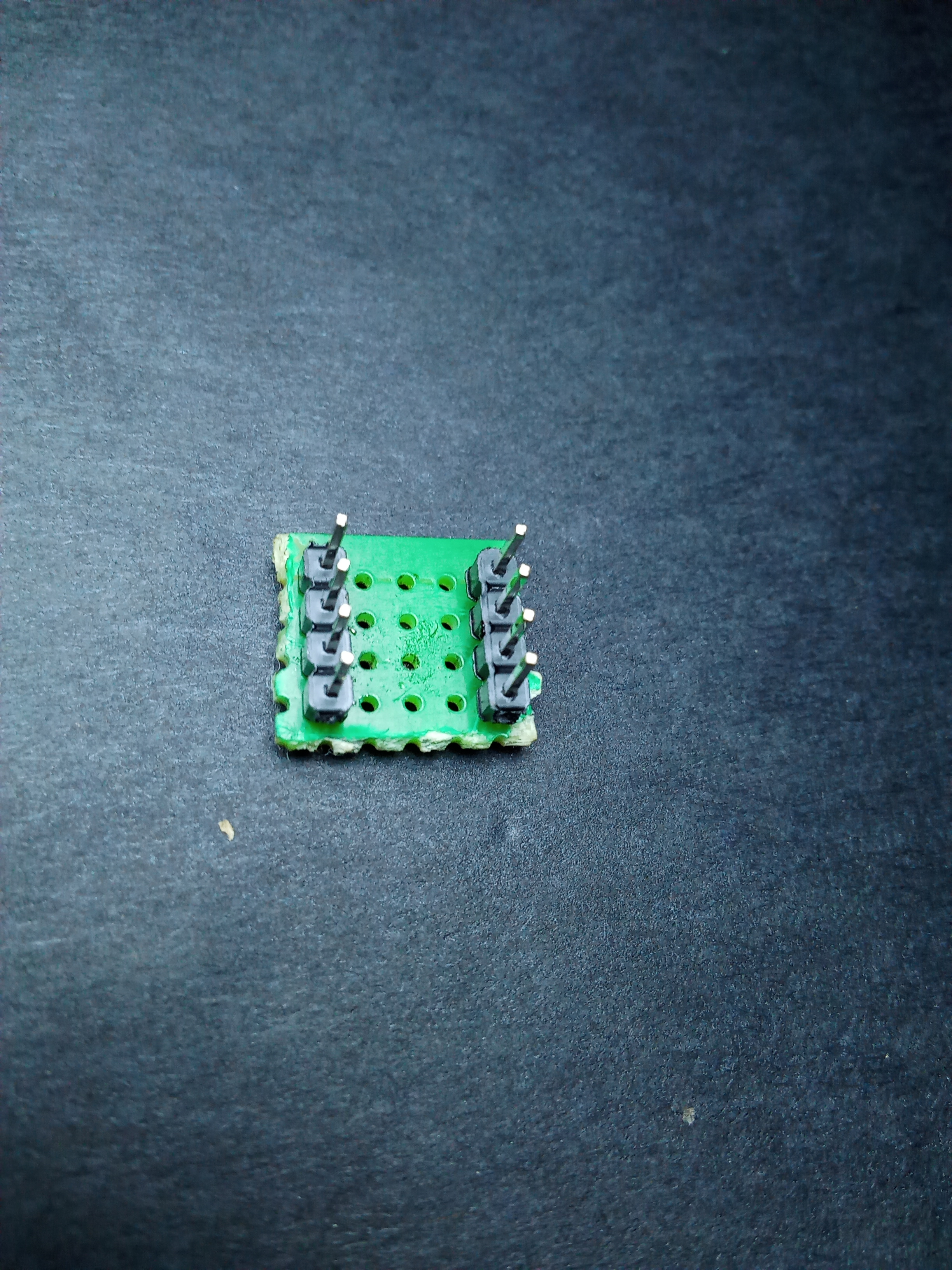
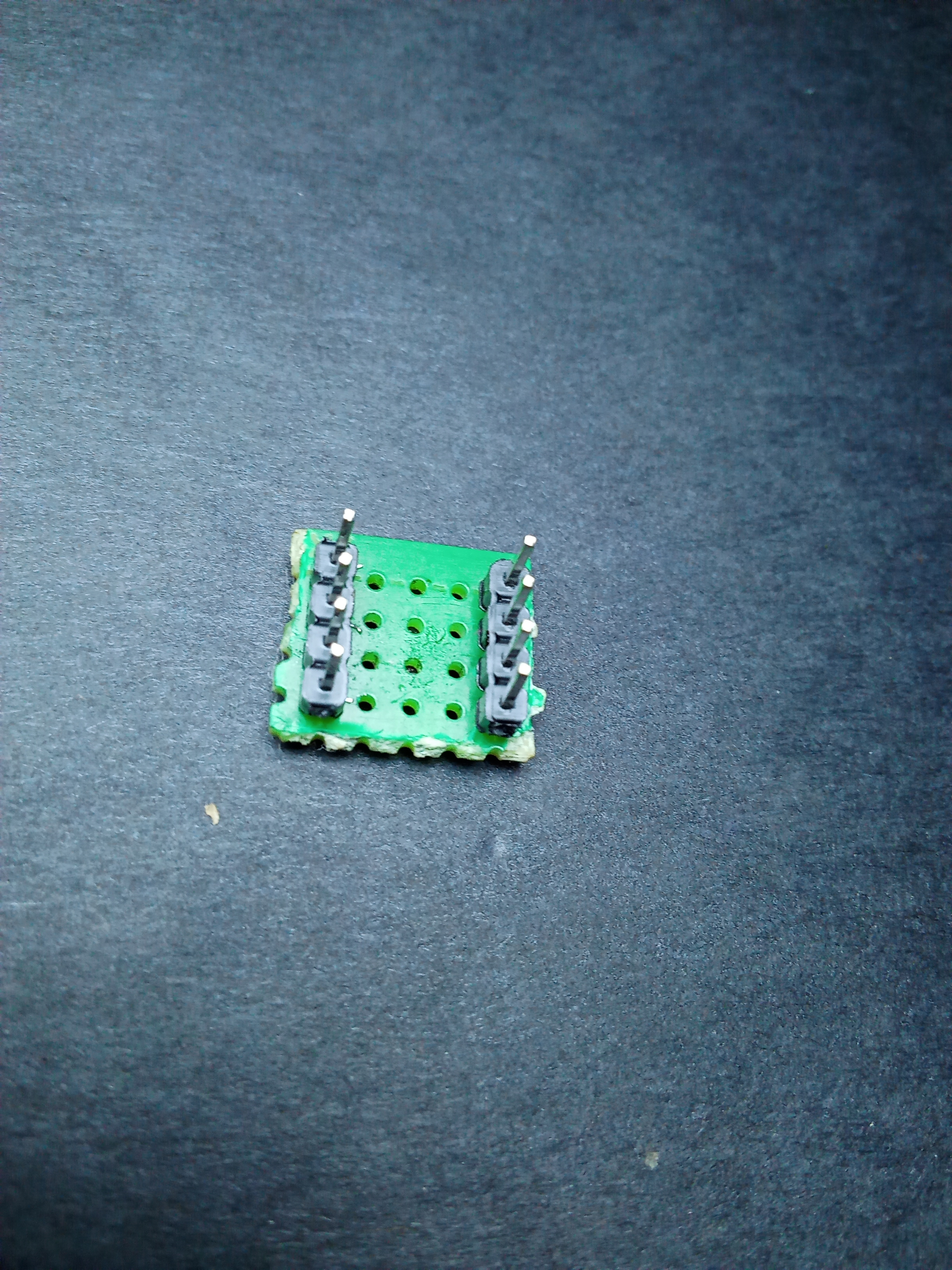
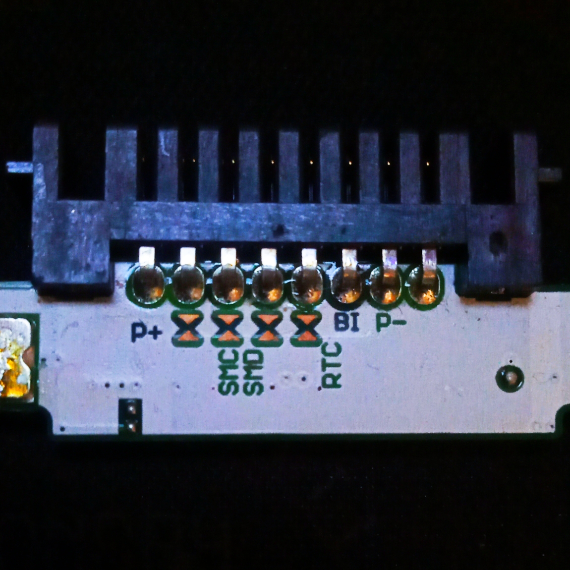
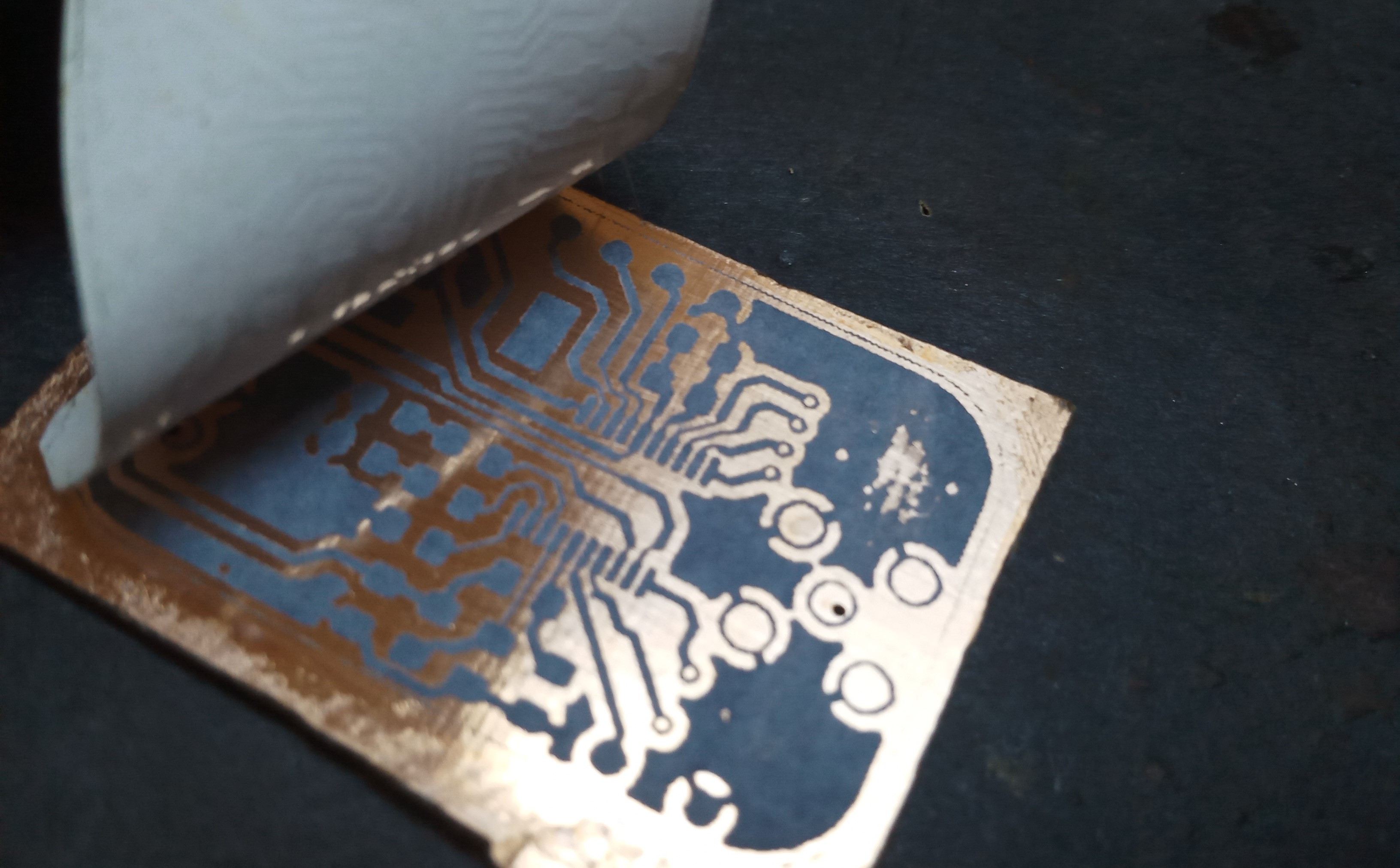
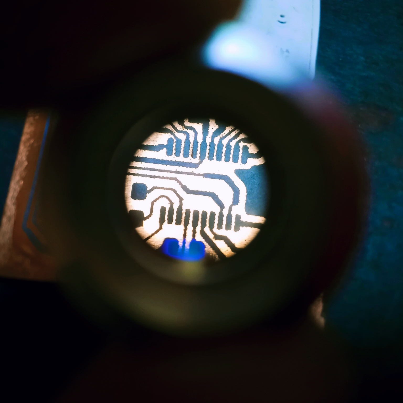
The CS4334 is an 8pin 24-bit 96kHz 2channel I2S DAC with a single 5V power supply. For lack of an interposer PCB I had to put my soldering skills to the test and improvise a breakout board for the IC from perfboard.
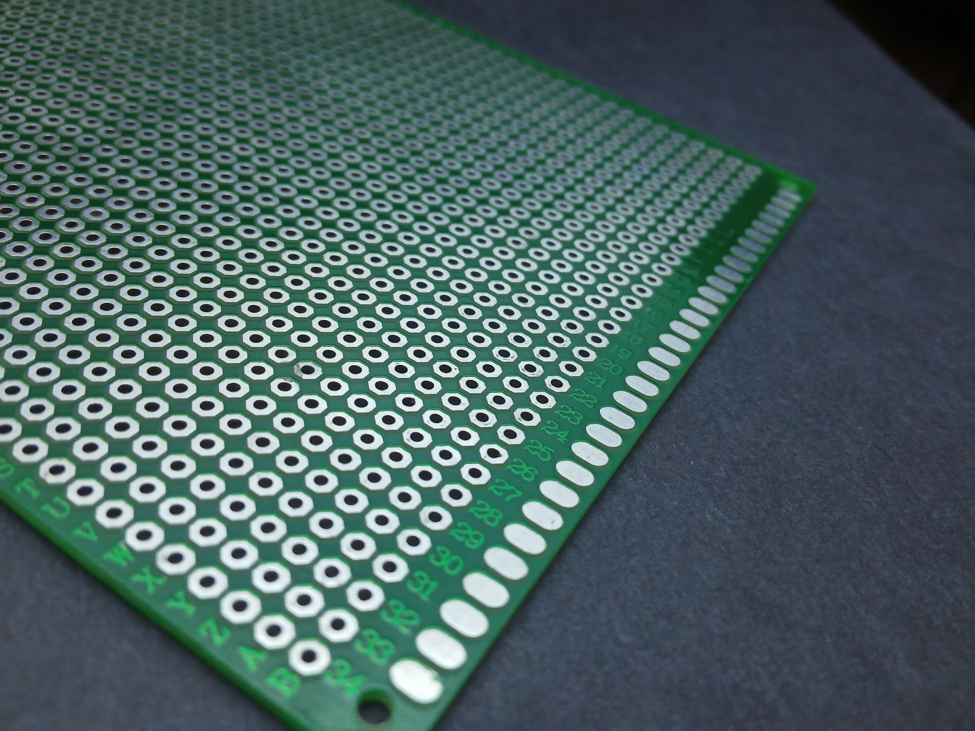
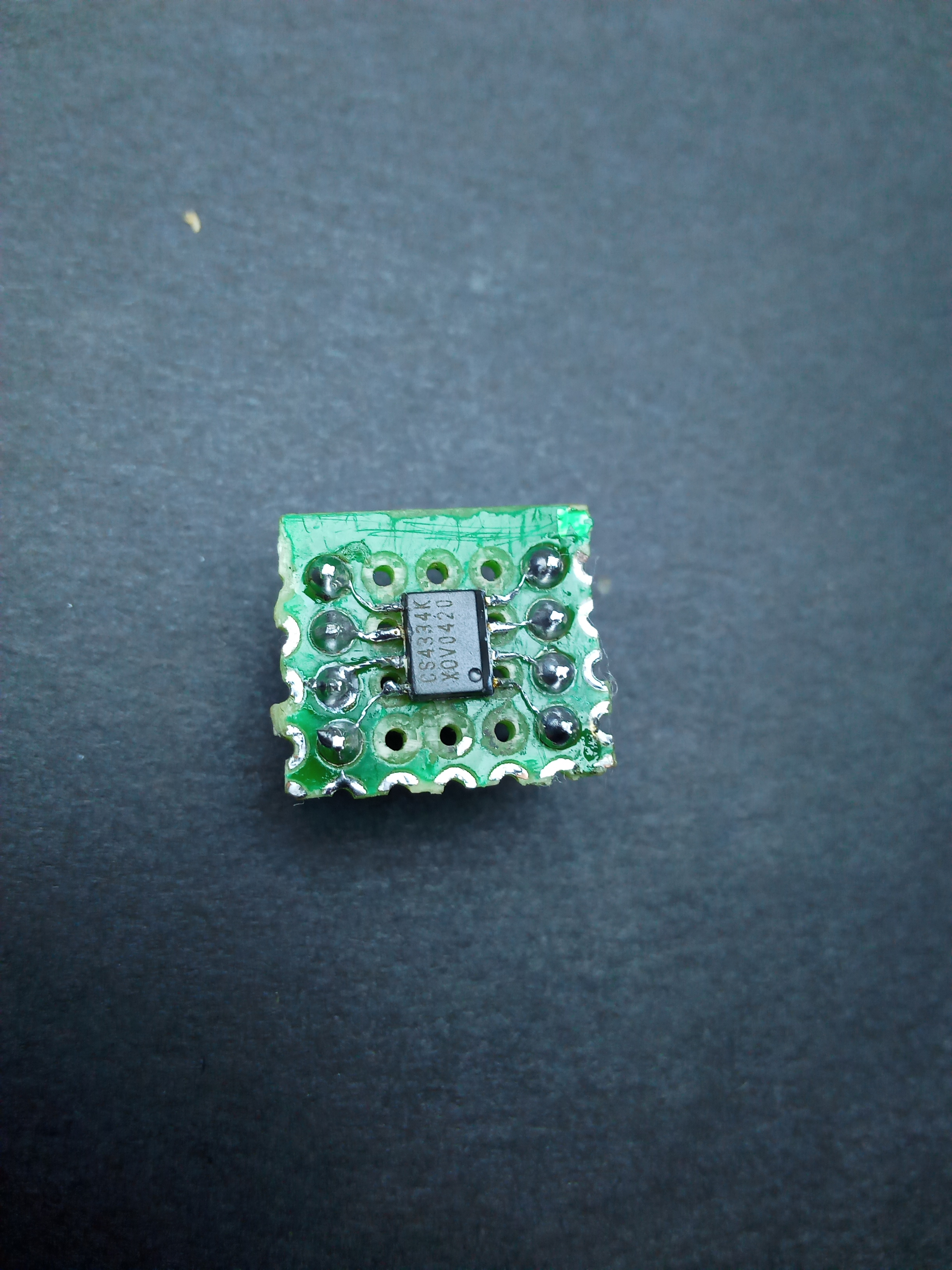
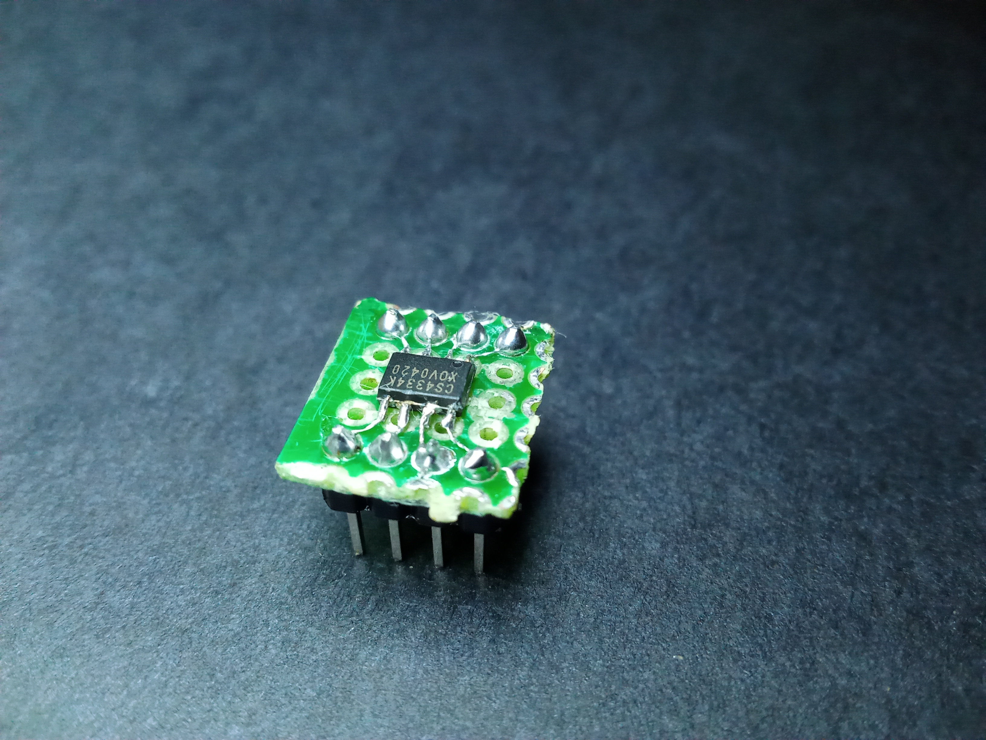
An unfortunate effect of soldering with an overheated iron is that it peels tracks right off the PCB, and this proved quite useful for removing copper from the areas where the chip would sit to prevent the leads from shorting during actual soldering. After that, it’a all a matter of patience and surgical accuracy to connect stranded wire between header pins and the IC leads.
Origin
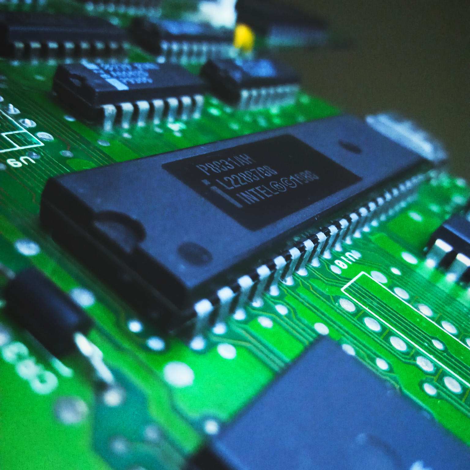
High quality CD Audio is standardised as 2 channels of LPCM audio each signed 16-bit values sampled as 44100Hz. In the modern CD Player, the physical disk is read by a digital device (a microcontroller controlling a laser module and sensor), we need a Digital to Analog Converter to obtain our audio (an analog signal). And that is where the Digital-to-Analog Converter (DAC) such as the CS4334 comes in. Lucky for us, the part of the player that often breaks down first is the power supply section so the DAC was still fully functional at the time of extraction.
In absence of the 4334, any I2S DAC can be used or you could even use the ESP32’s built-in DAC(at the cost of resolution).
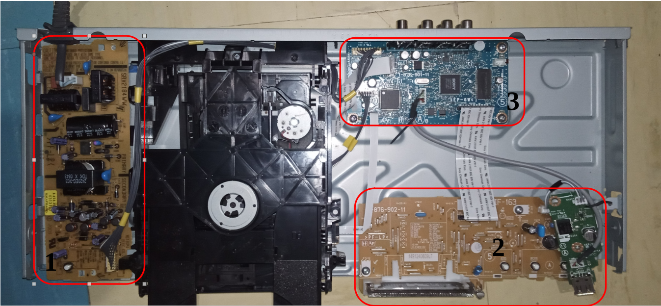
Here we have the general structure of a DVD player: 1.Power supply (SMPS) with 12v, 5v and 3v output. 2.The interface board, with pushbuttons, leds, IR receiver for remote control, USB and a display. 3 Last and most important is the motherboard, which carries the MCU, Motor driver, Opamp and our object of ReFab: the DAC.
The Build
Parts required:
- Any ESP32-based board
- CS4334
- Capacitors (any value above 10uF works)
- Breadboard with 5V power supply
- USB cable for programming
- Smartphone with FrequencyGenerator app
Hardware Configuration
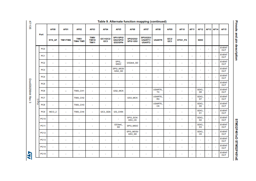
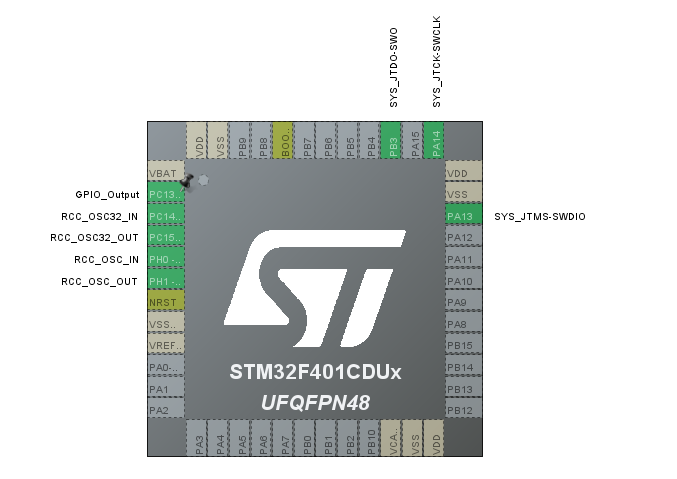
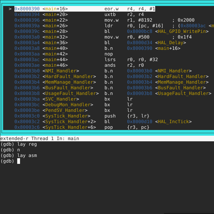
The CS4334 uses I2S, a serial communication protocal tailored specifically for the transmission of high quality audio thus requiring an MCU with said peripheral. I started with my then default development MCU, the STM32 Mini F401 spec’d to have two I2S peripherals only to find out that the UFQFPN48 package provides no access to the MCLK pin:
Thus I settled on the ESP32 at it was the only other MCU at hand with I2S. A intriguing discovery I made at this point is that it is possible to assign the hardware connection of a peripheral to any pins of your choosing, that is, with a few exceptions such as pin 34 & 35 which can only function as inputs thus cannot be used for peripherals’ output pins.
Another exception more relevant to this project is the I2S MCLK pin which can only be assigned to GPIO0, GPIO1 or GPIO3, and the only ones accessible on the pinout of the ESP32 Devkit board are GPIO1 & GPIO3 used for esp-console TX &RX.To enable monitoring from the PC, I chose GPIO3 for I2S MCLK.
Pinout:
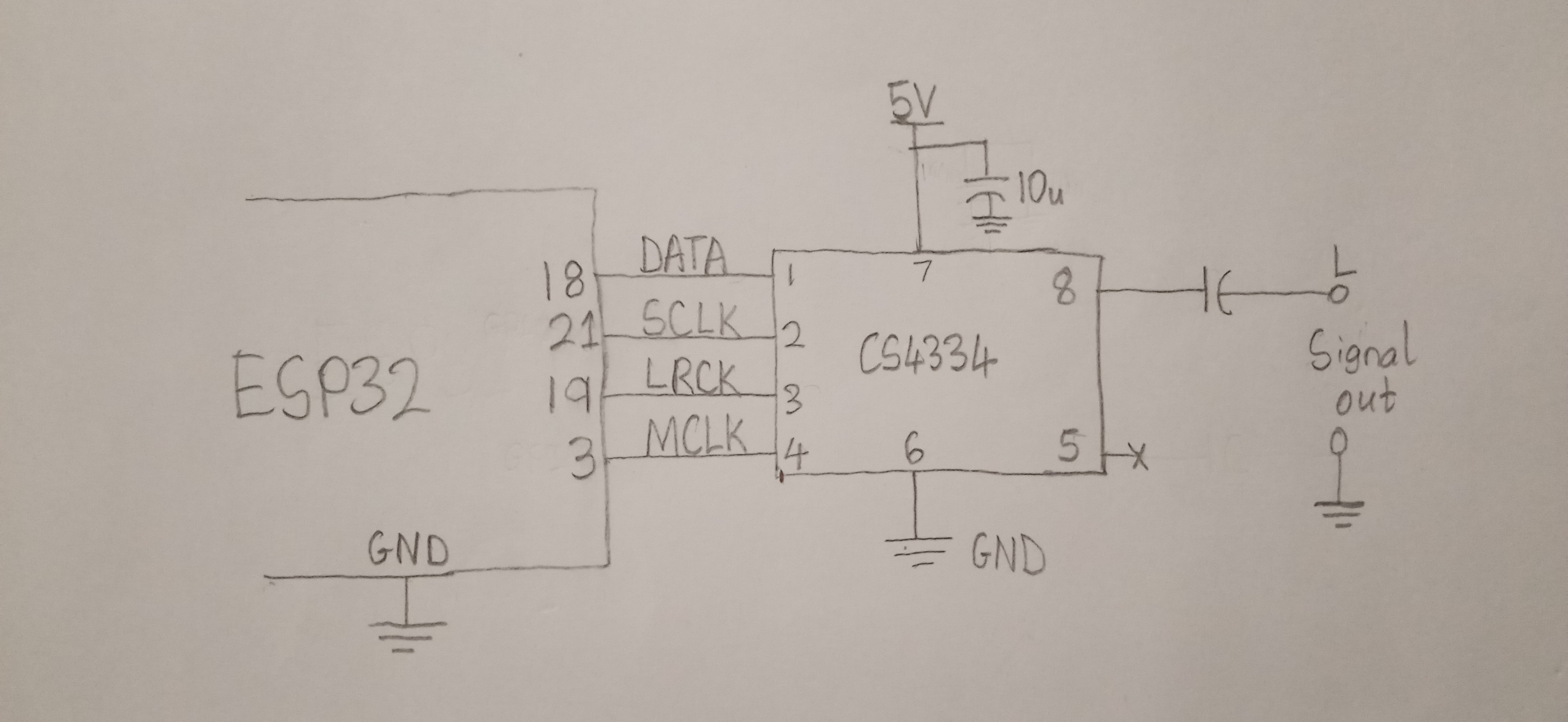
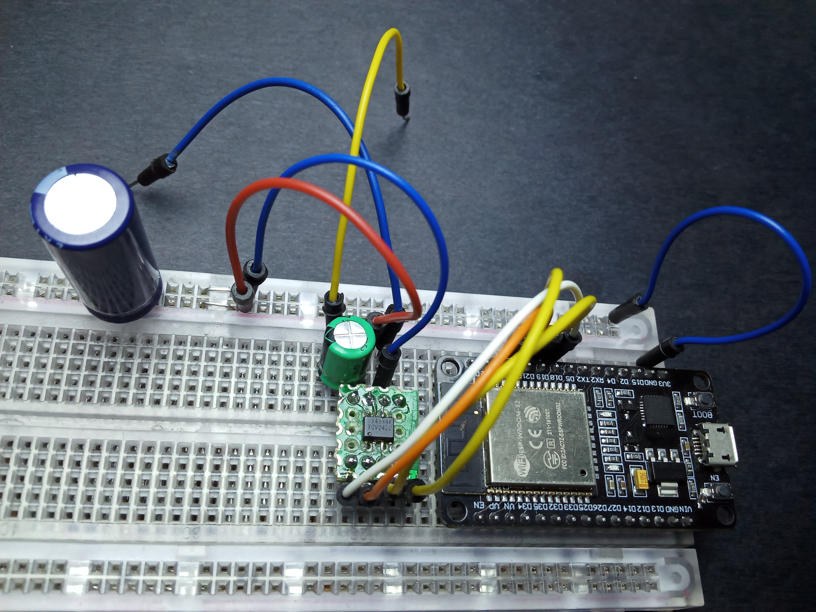
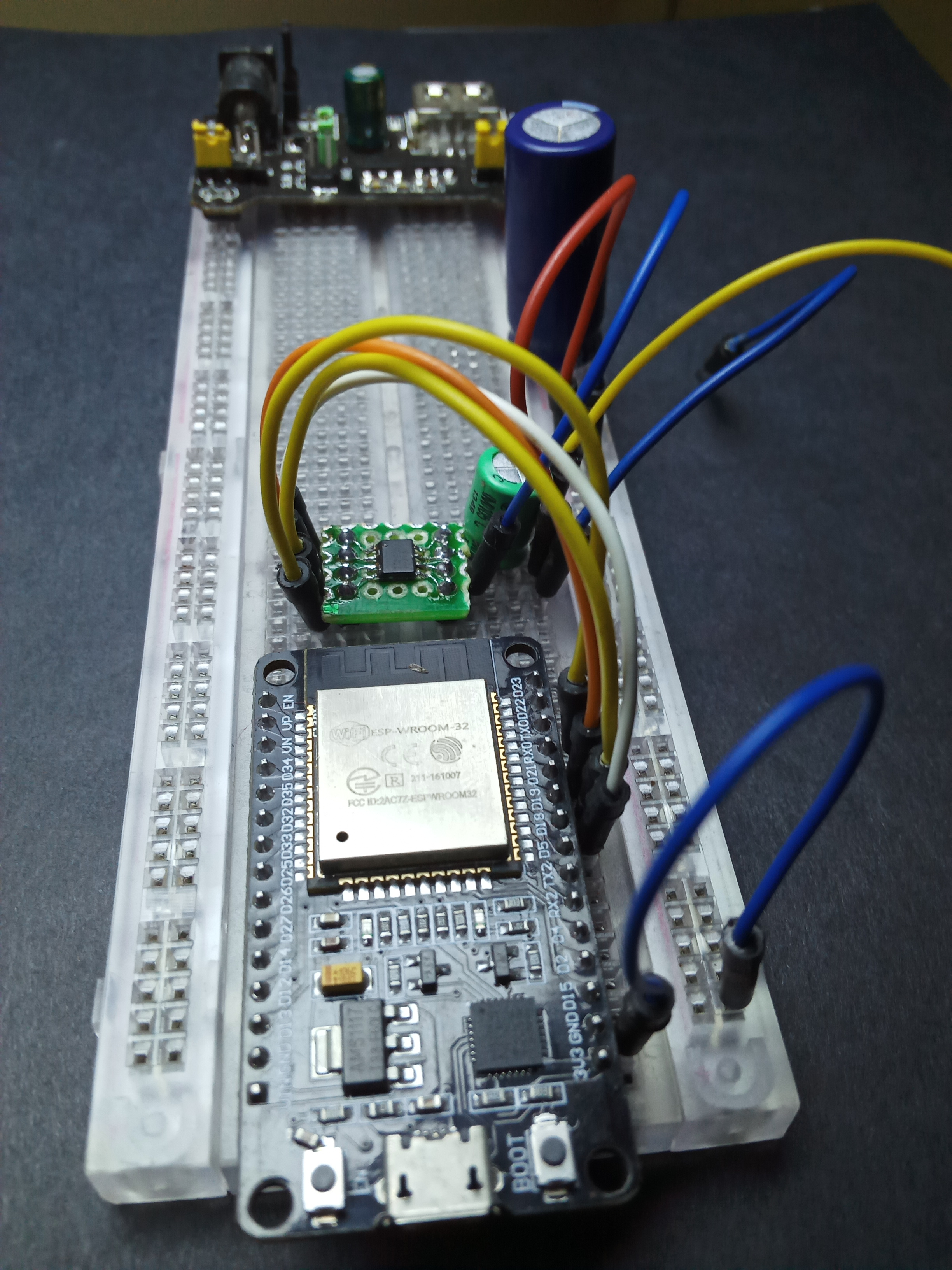
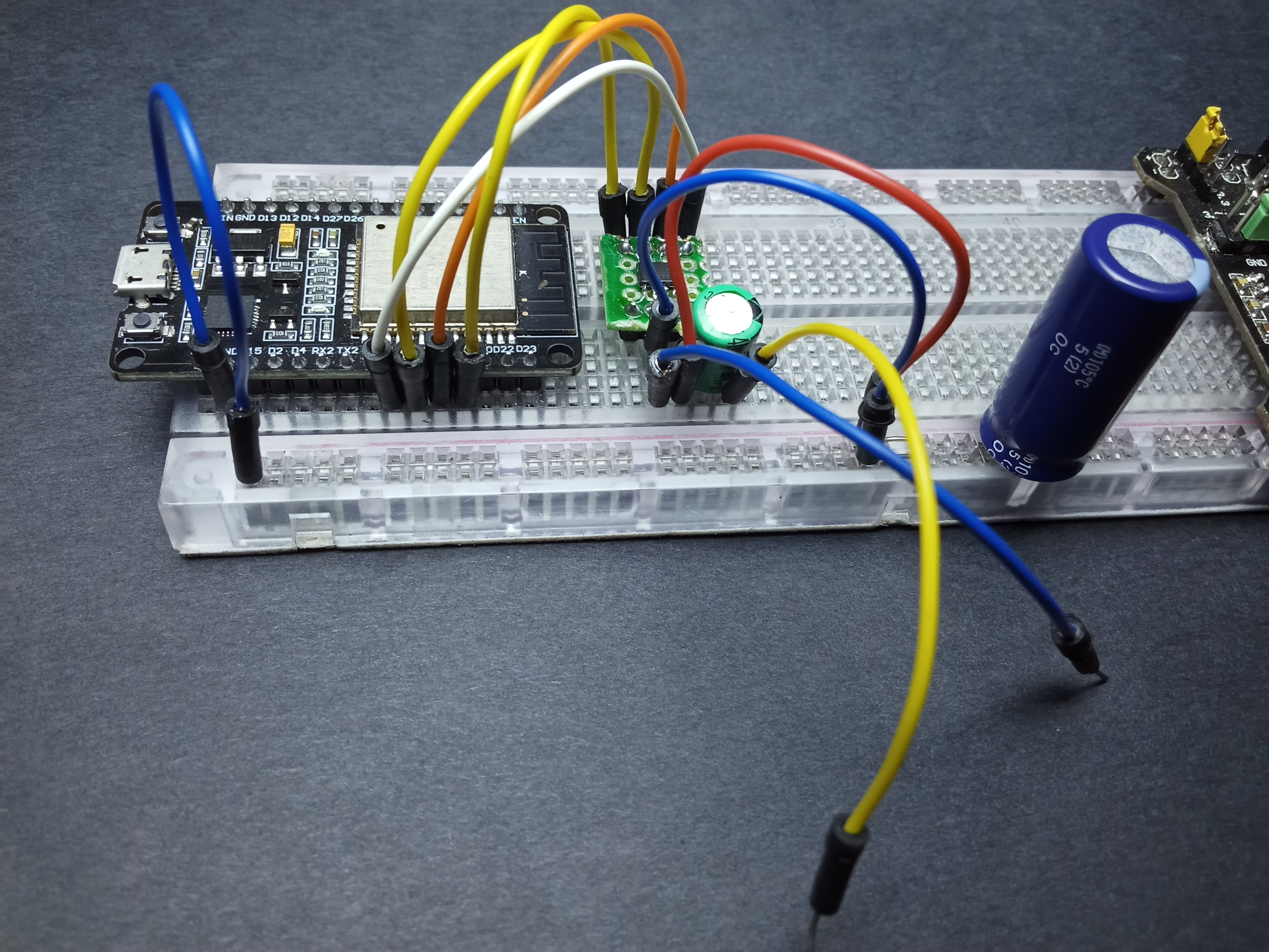
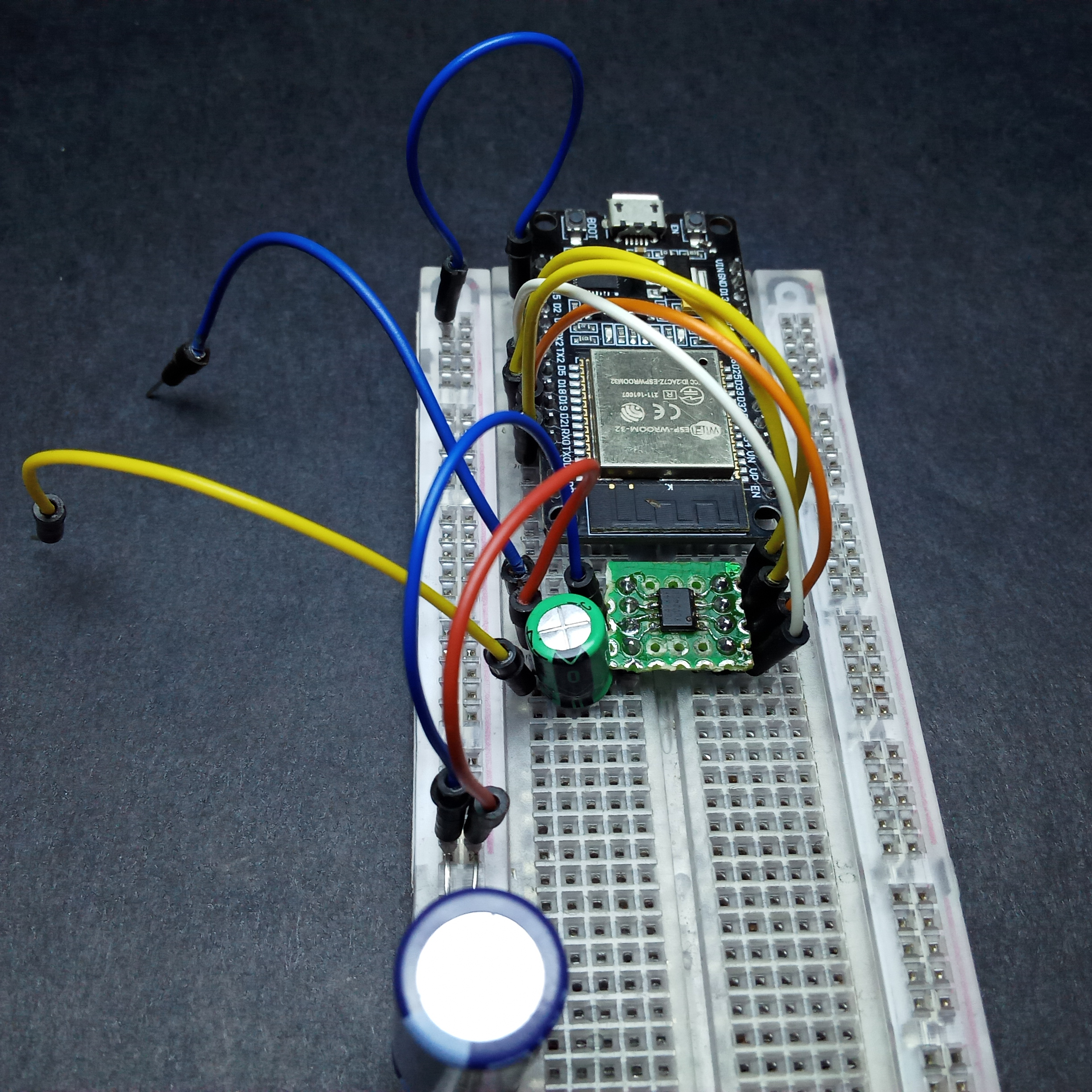
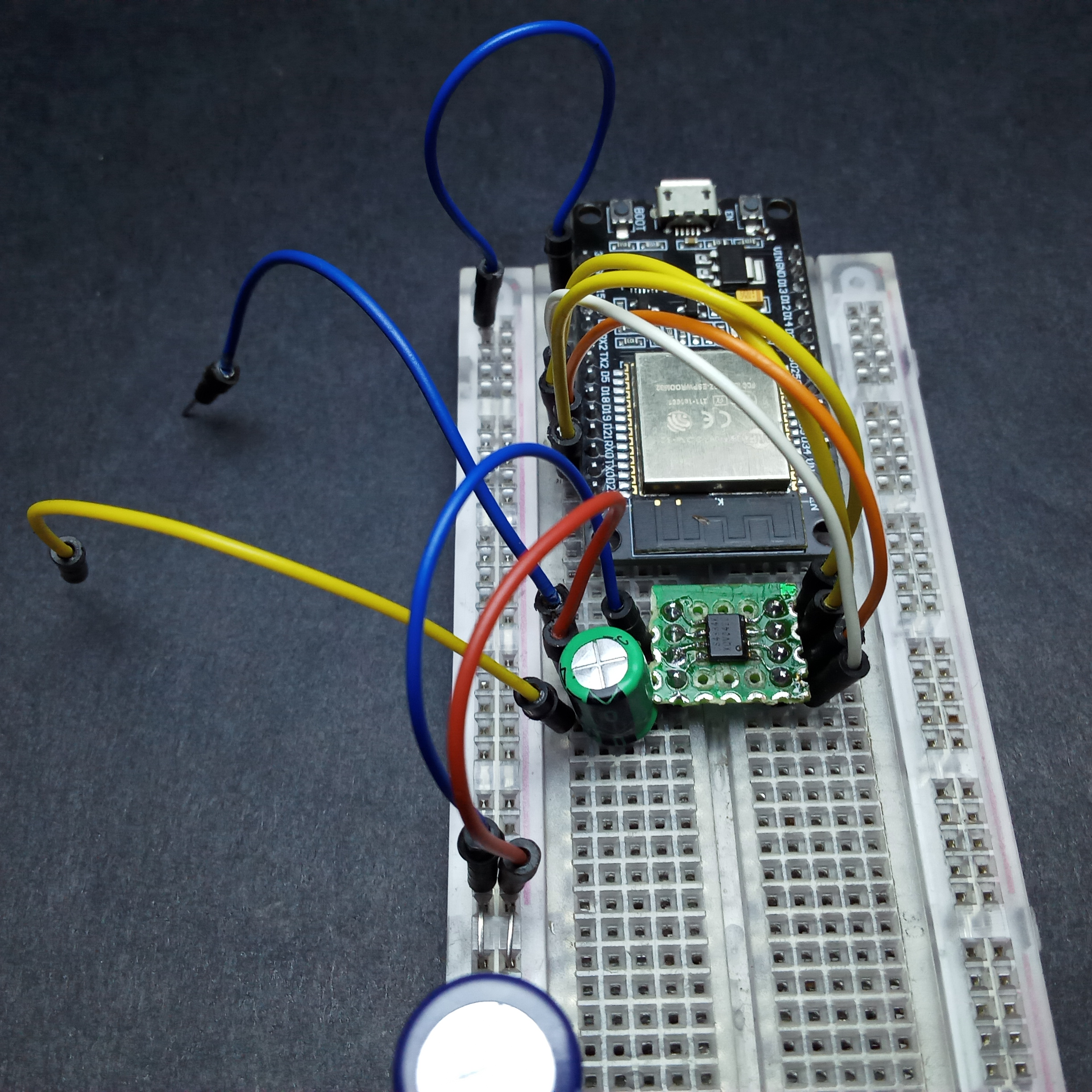
Connect the devices as shown below:
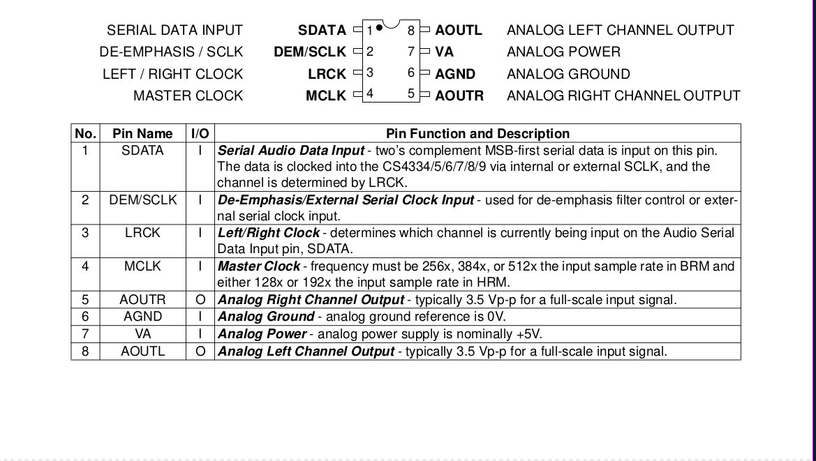
I2S pins of the CS4334 (5V) are all input pins therefore no logic level shifting is required when connecting with ESP32(3V3).
Connection diagram:
Software Configuration
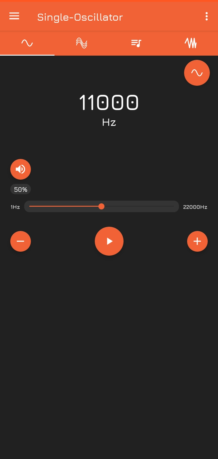
The audio signal we’ll be using is generated by a feature-packed Function Generator app that can be downloaded from the Play Store.
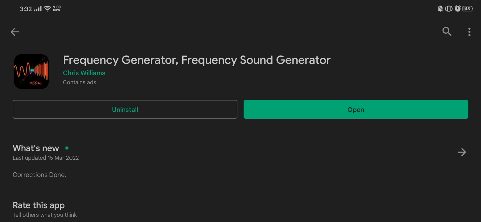
Any function generator app would serve our purpose well, but I preferred this one as on account of it’s features:
- frequency range from 1Hz to 22kHz with a 1Hz resolution
- capable of generating a Square wave, Sine wave or Triangle wave (all of symmetric half cycles)
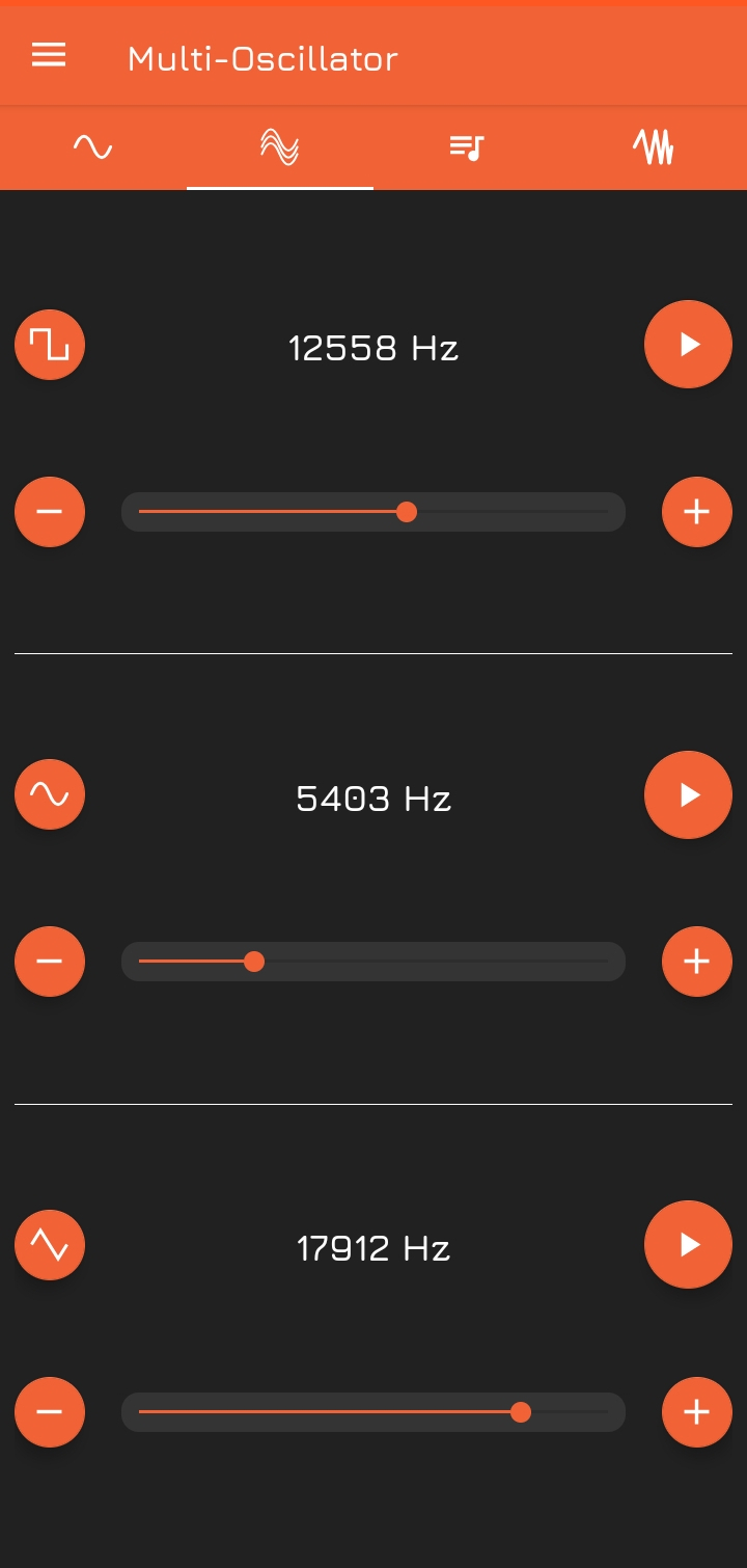
- ability to superimpose upto 3 waves of arbitrary frequency and waveform
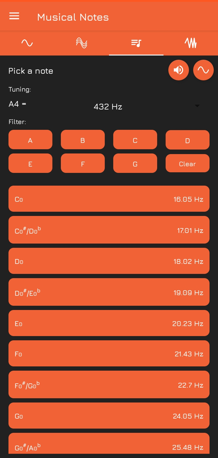
- generating musical notes
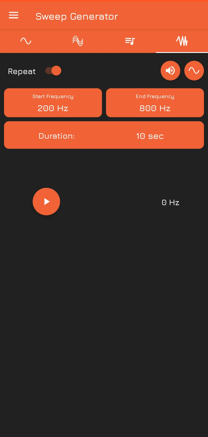
- A frequency sweep of custom frequency, waveform and duration
- Wireless operation
Having installed ESP-IDF, clone my repo and open IDF in the cloned directory. To configure the project, run
idf.py menuconfig
and:
-
Set the use of external I2S codec or internal DAC for audio output, and configure the output PINs under A2DP Example Configuration
-
Enable Classic Bluetooth and A2DP under Component config –> Bluetooth –> Bluedroid Enable
Build the project and flash it to the board, then run monitor tool to view serial output.
idf.py -p PORT flash monitor
Turn on Bluetooth on your smartphone and search for BT_SIG_GEN. Accept the pair request, then open the Function Generator App. Our auido signal generator is now ready to roll!
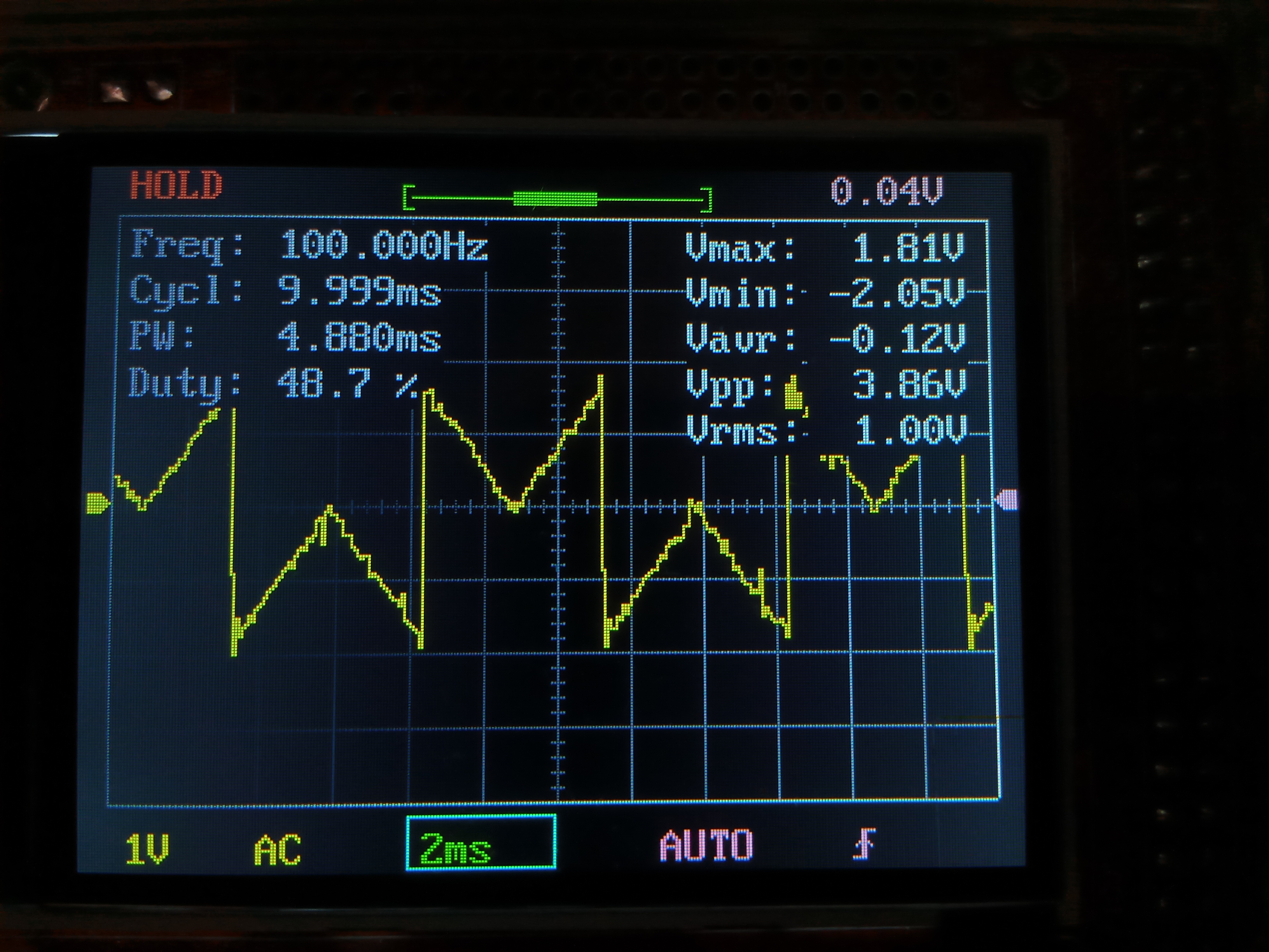
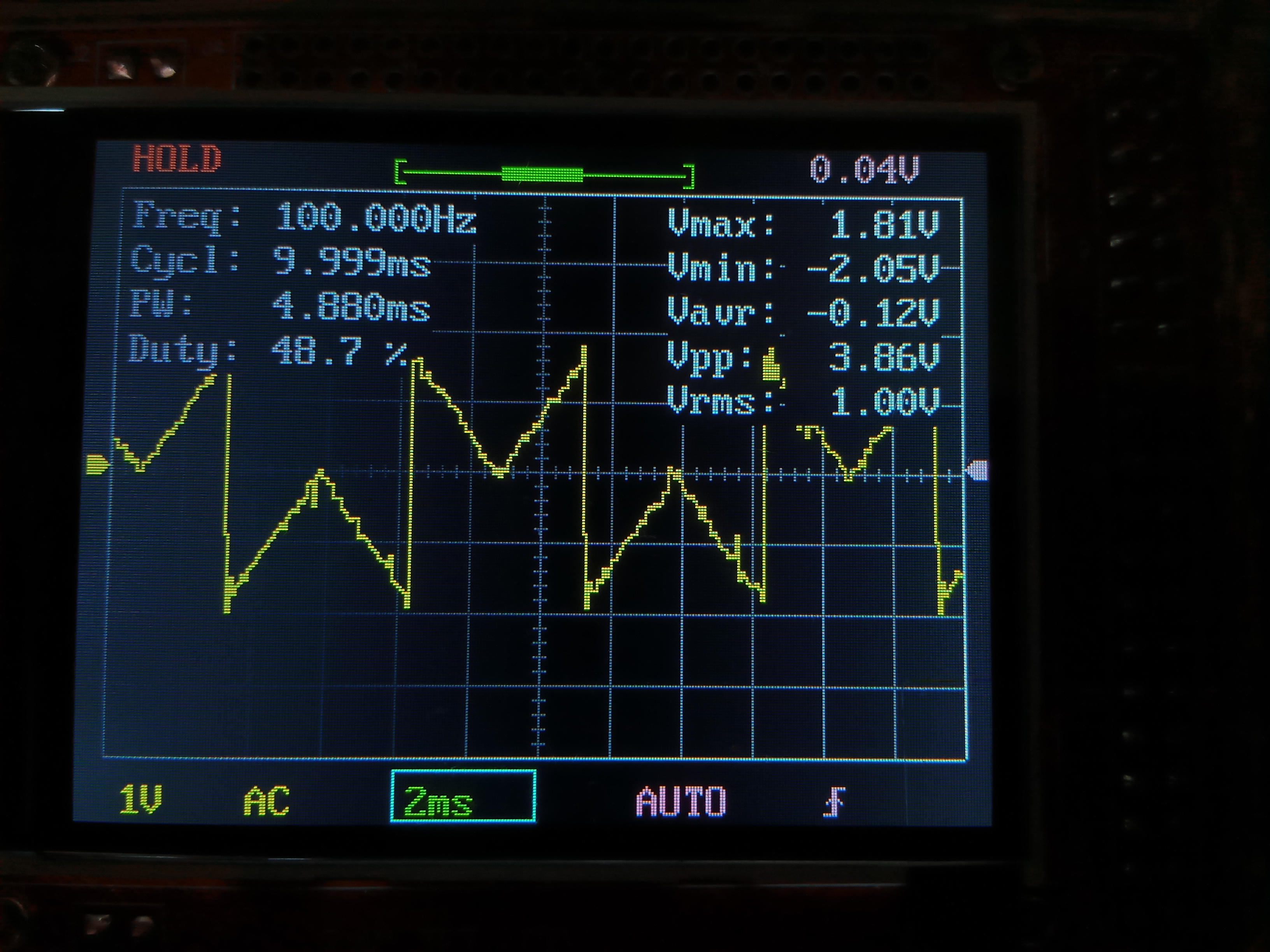
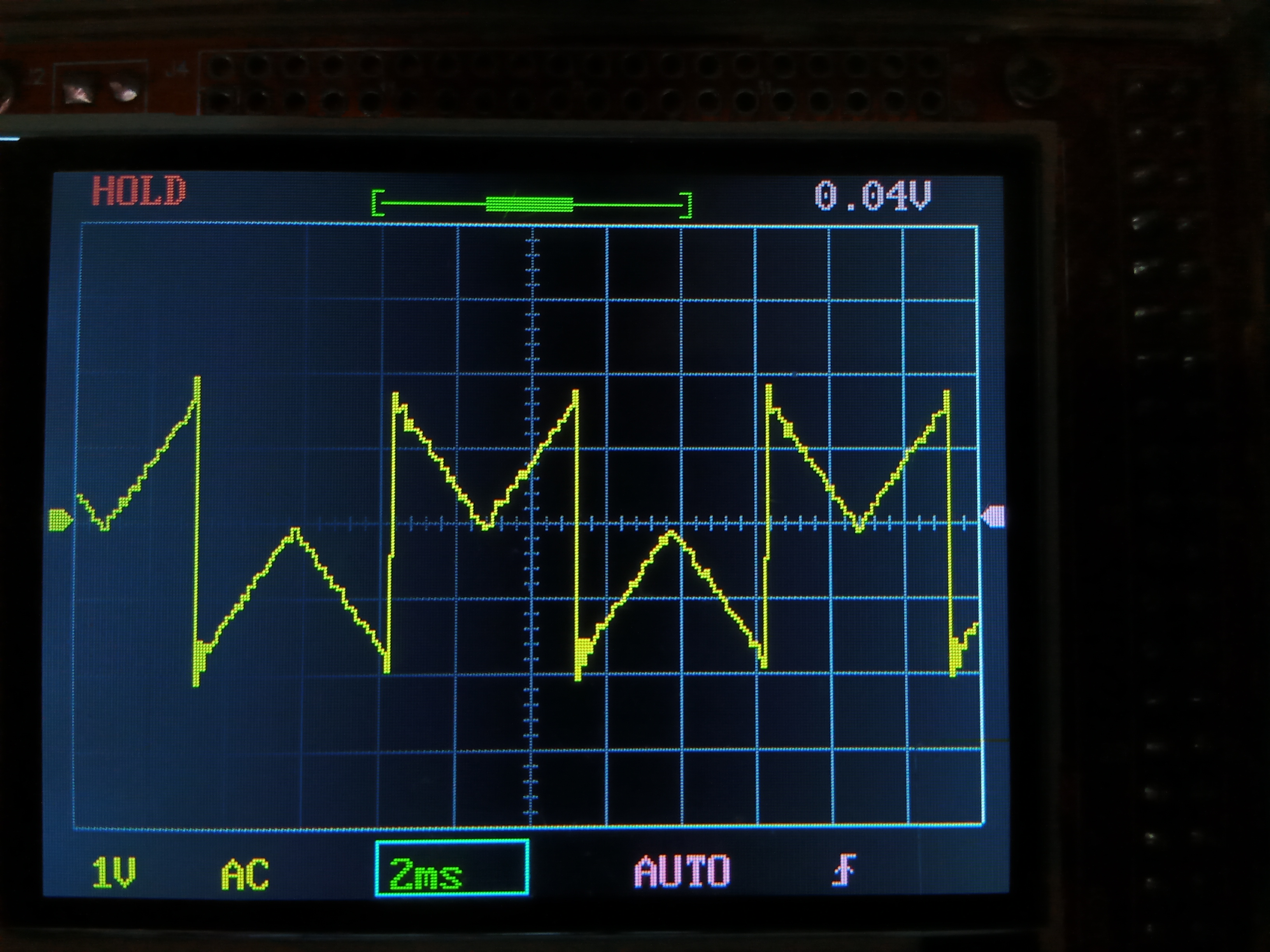
Results
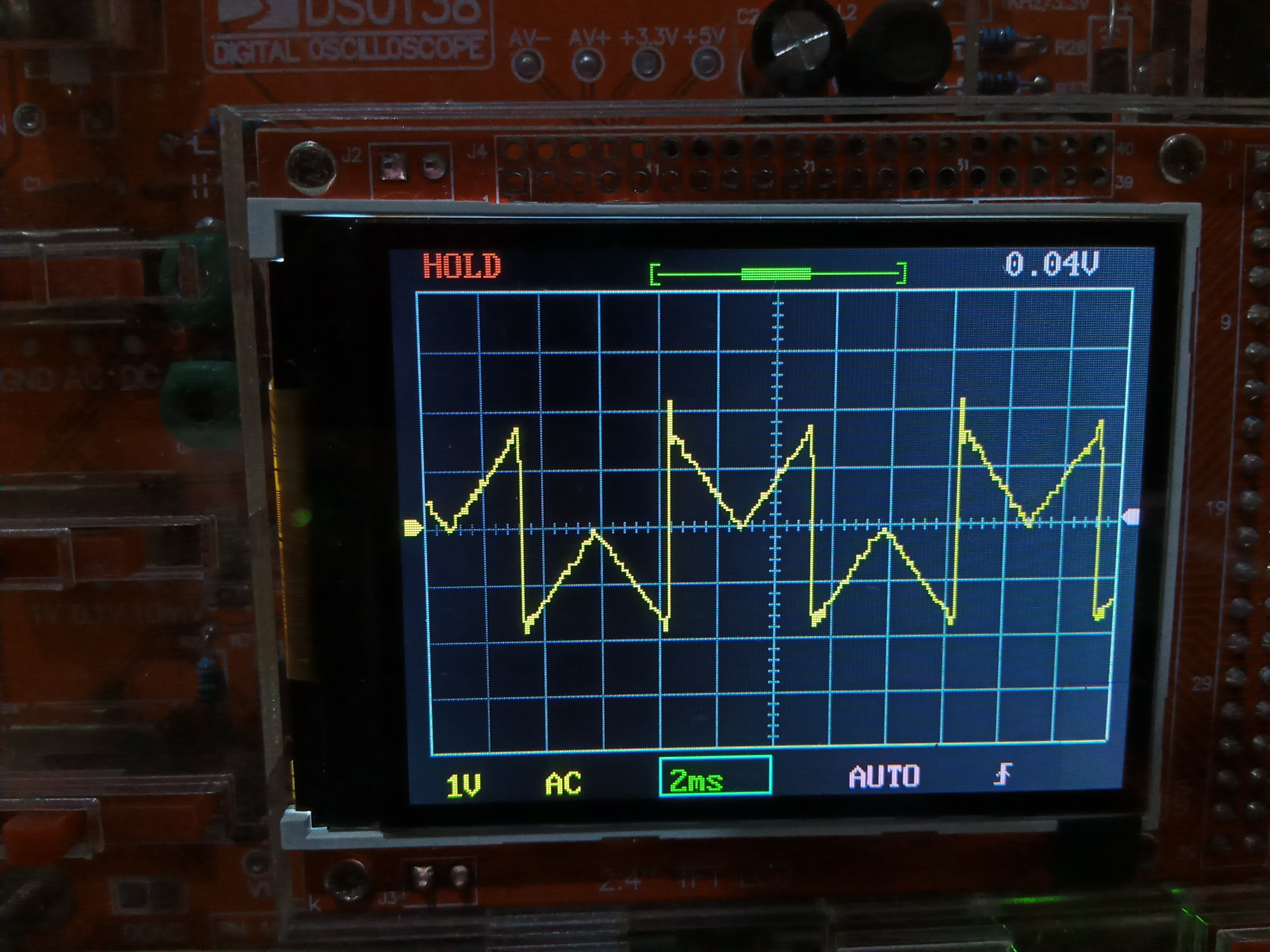
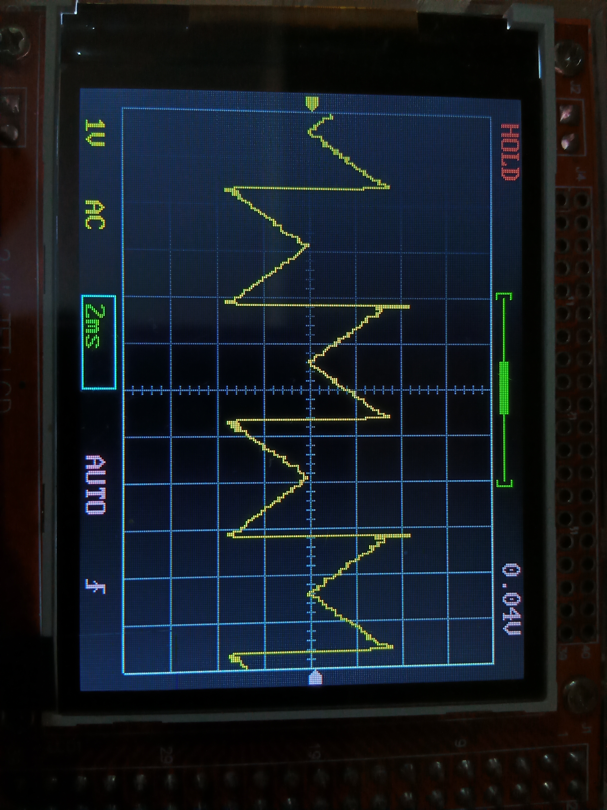
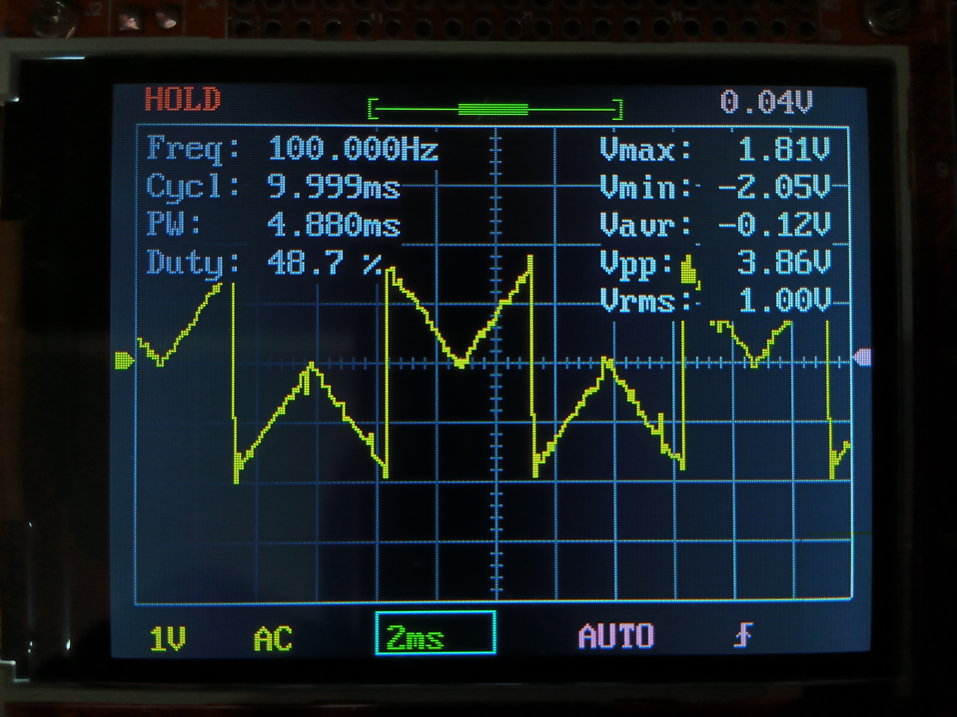
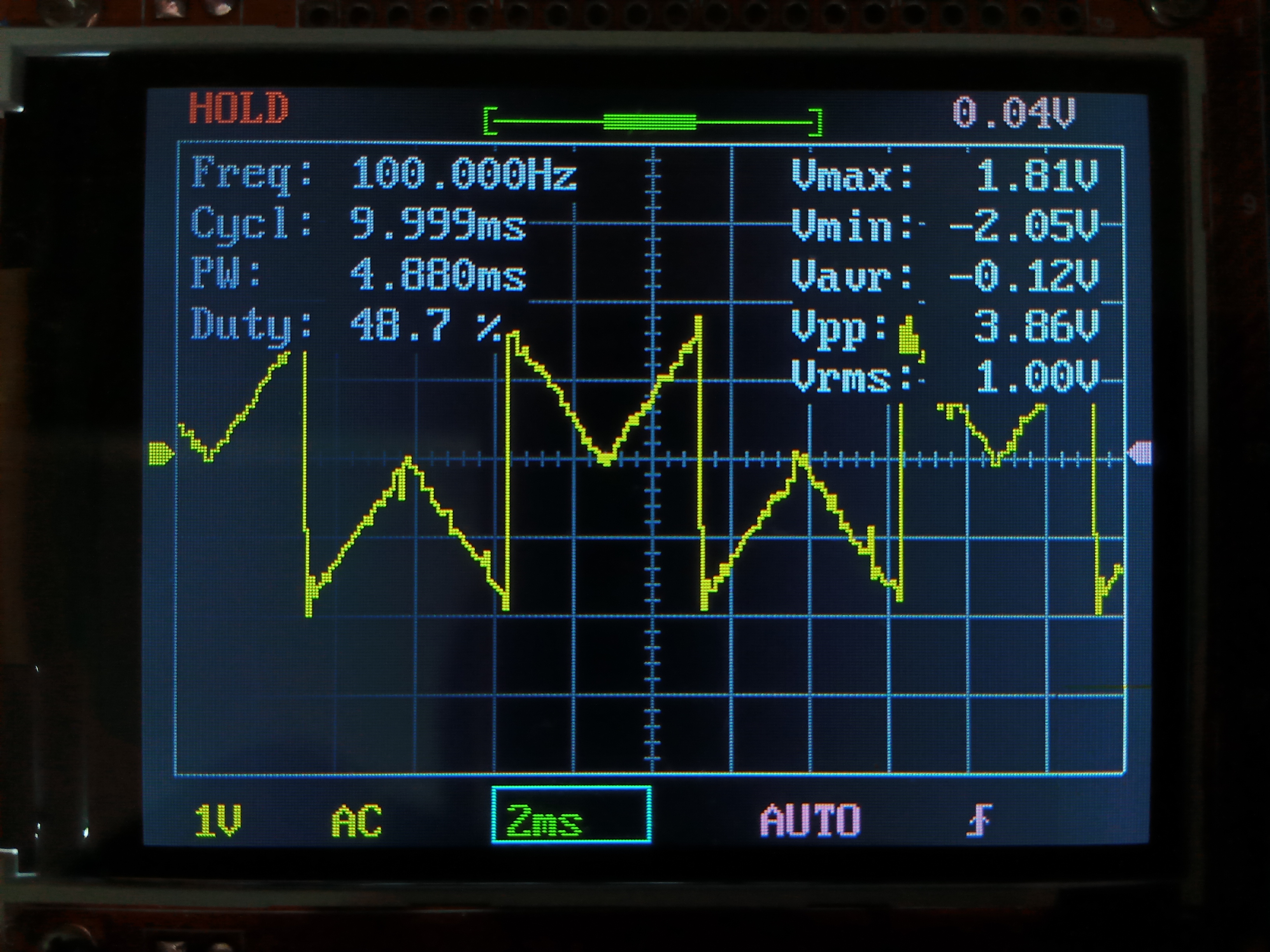
Here’s three different waveforms output at a frequency of 4013Hz (because, well, why not).
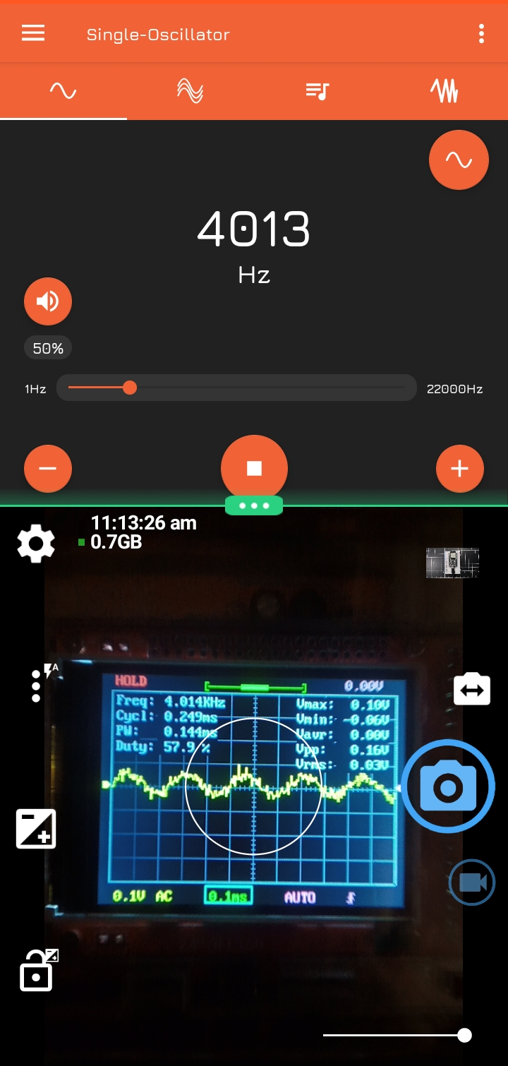
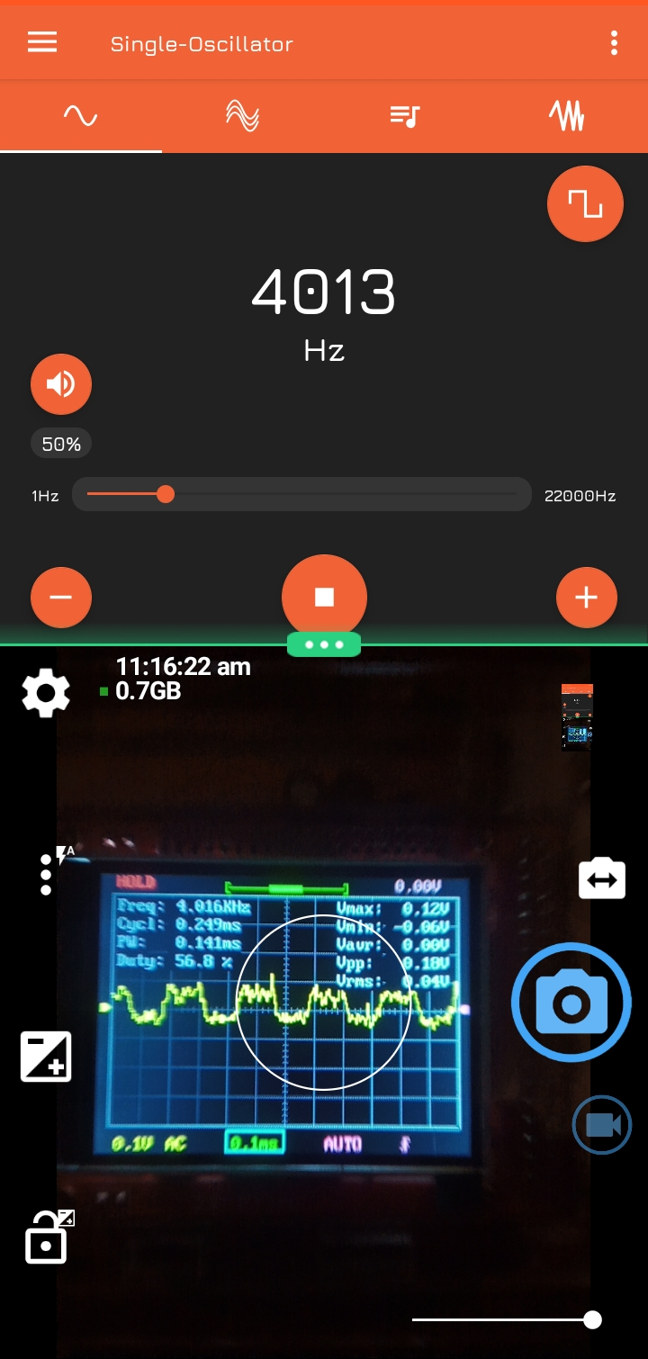
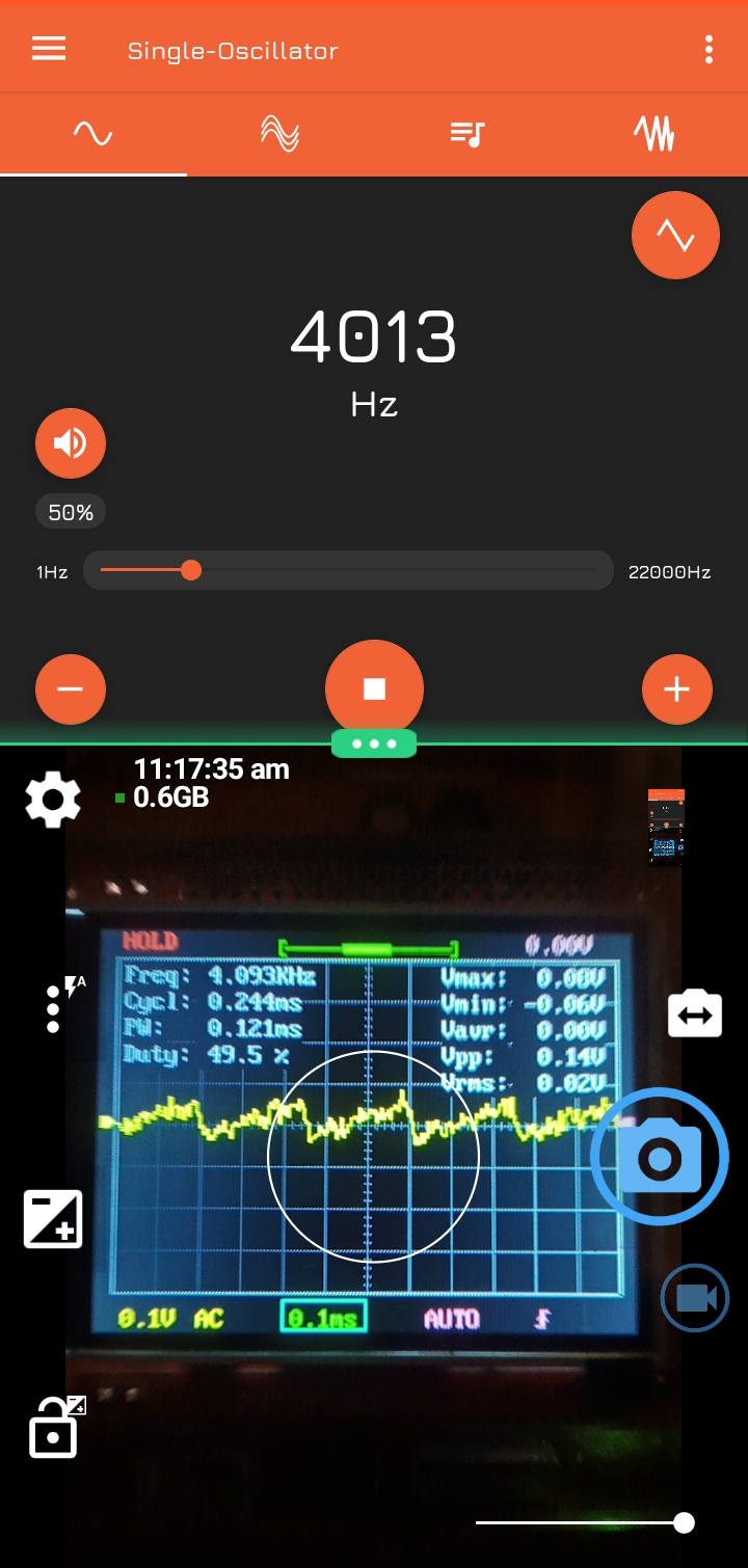
A much cleaner output can be obtained using an inductor filter circuit at the DAC power supply.
Takeaways
I finally got an excuse to use ESP32’s native development environment, ESP-IDF and shed away Arduino’s layers of abstraction. This was one of my favourite gains from this build as it ushered me into a new world I have yet to explore. For a first experience with the I2S interface, this proved particularly confusing because it took me a while to come to terms with how simple the protocol is (having got used to protocols like SPI & I2C).
Conclusion: This project-based learning is a key component of the ReFab lifestyle and just do happens to be the type of learning I gain best from.
References:
Project Gallery

Comments