Swimming through time with the FishTail - Part 1 (Building the FishTail)
Before the artistic sci-fi rendition of time travel we have grown so familiar with, there was - and still is - a more realistic, yet just as powerful practice in the context of software and hardware development. Debugging is the practice of finding and fixing bugs in software developed for a computer system. In embedded hardware development, bugs resulting from logical errors can be especially difficult to find as the code compiles just fine but the hardware fails to behave as expected. This is where a debug probe comes in: a debug probe allows the programmer to (relatively) stop time for an embedded device mid-execution and step through code running on it line by line, inspecting the changes that each line makes to the state of the hardware. Additionally, changes can be made directly to the hardware (e.g. pulling a pin high or low) allowing the programmer to test individual functionality components of the hardware (e.g whether the point of failure is the pin itself or external hardware).
In this tutorial, we build a debug probe for ARM-based devices that will allow you to program and debug your target microcontroller wirelessly (over Wi-Fi). In a future tutorial, we shall get into the specifics of ARM debugging and how to use the FishTail Probe.
The name
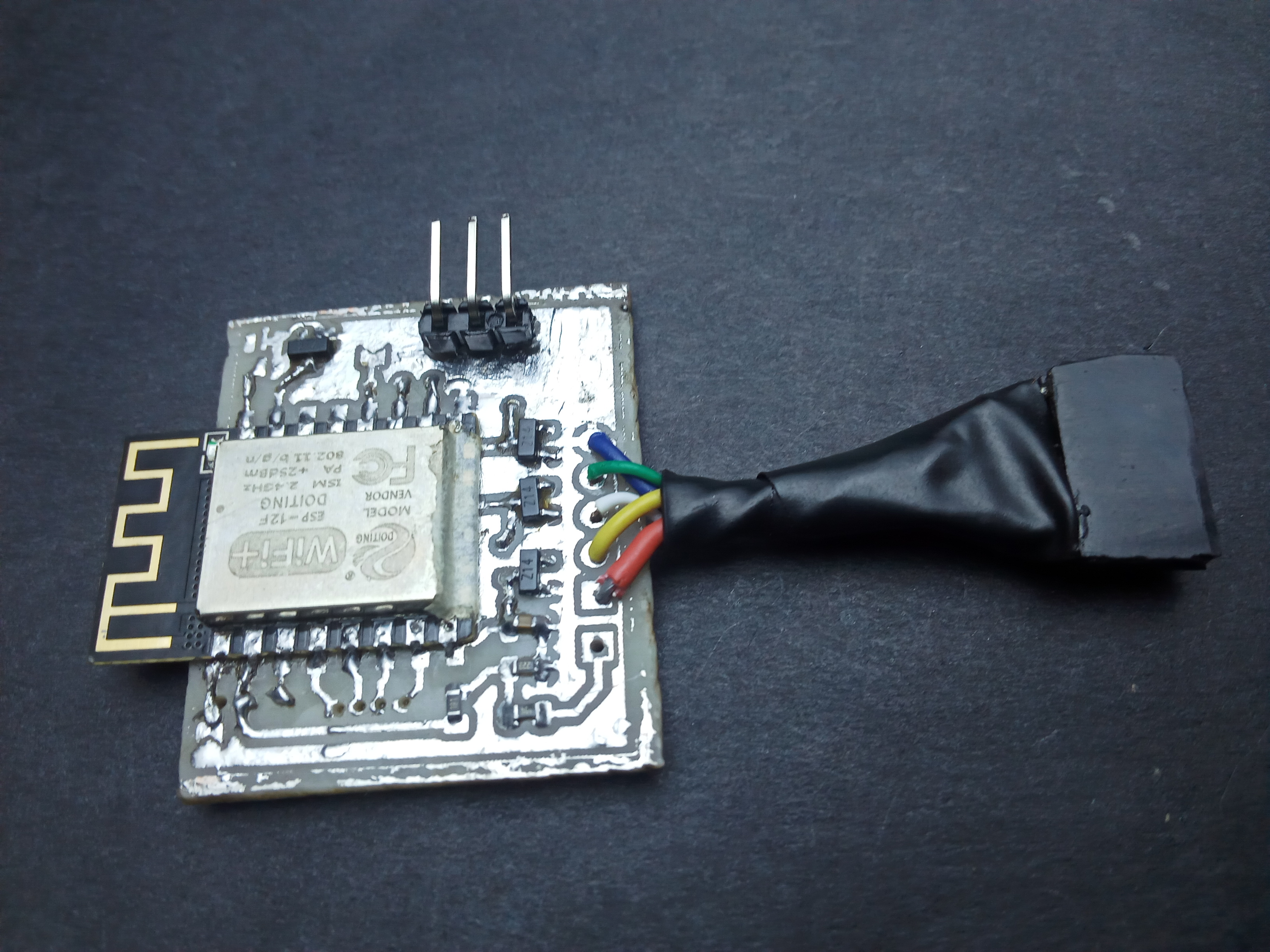
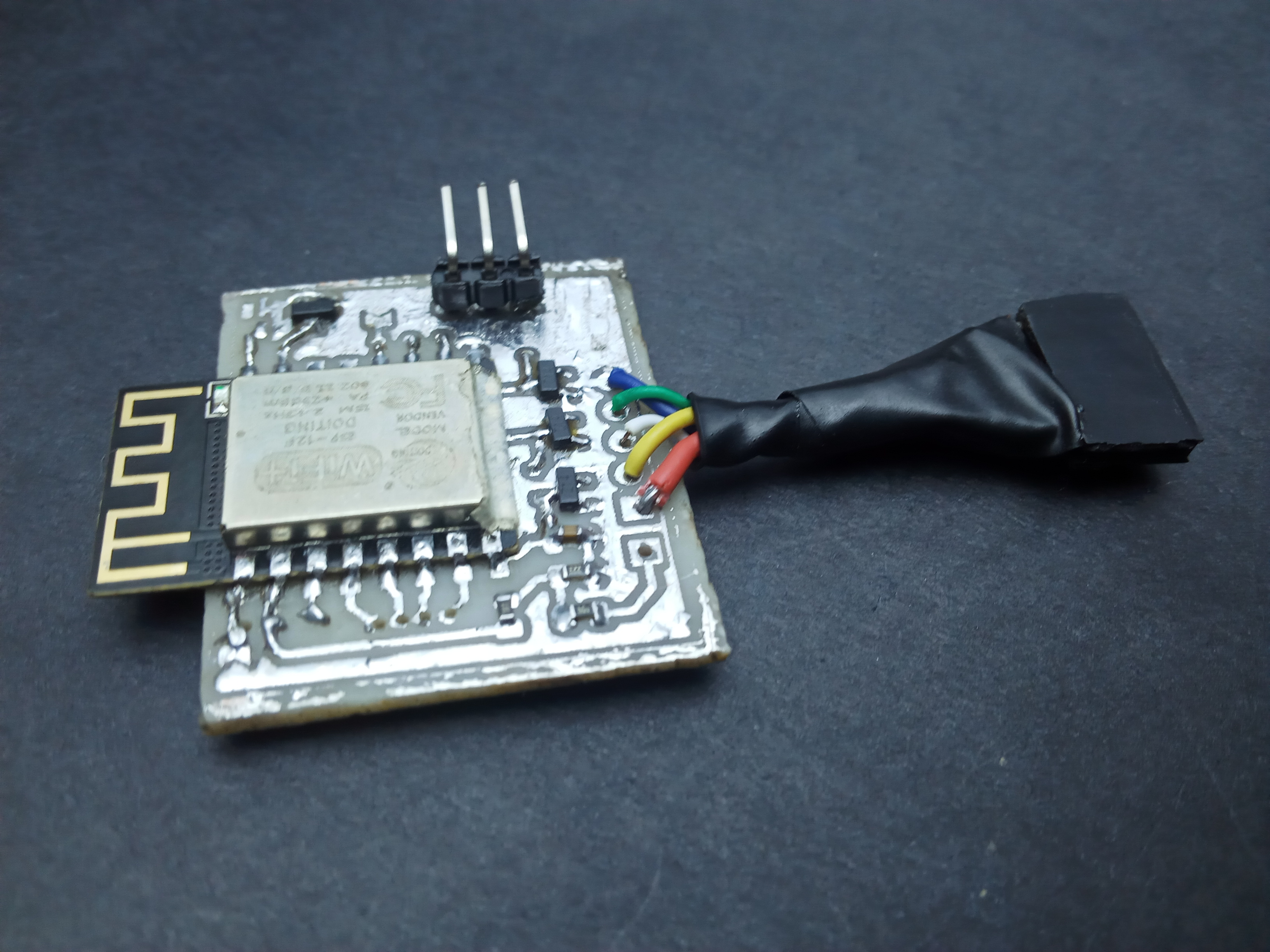
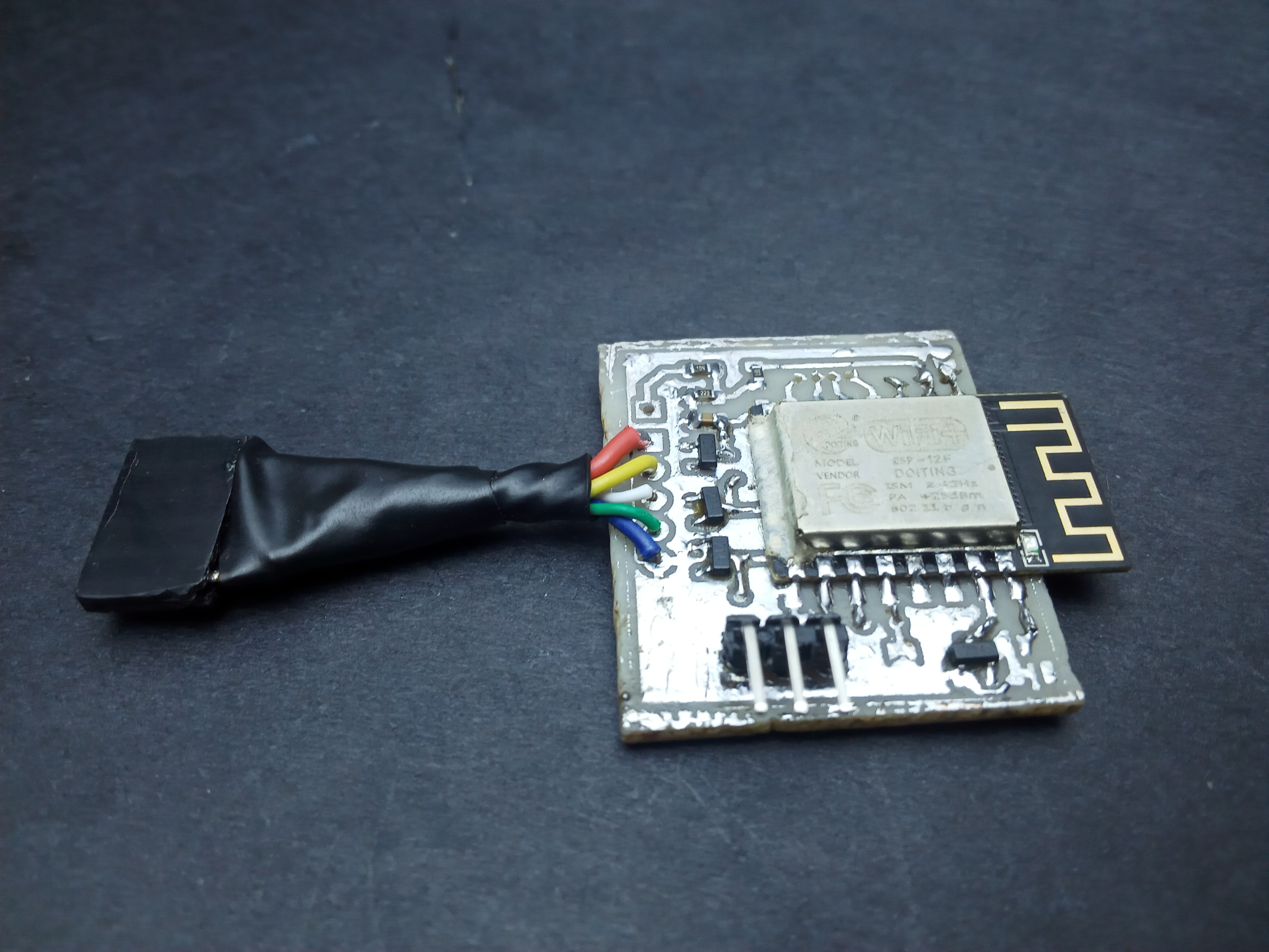
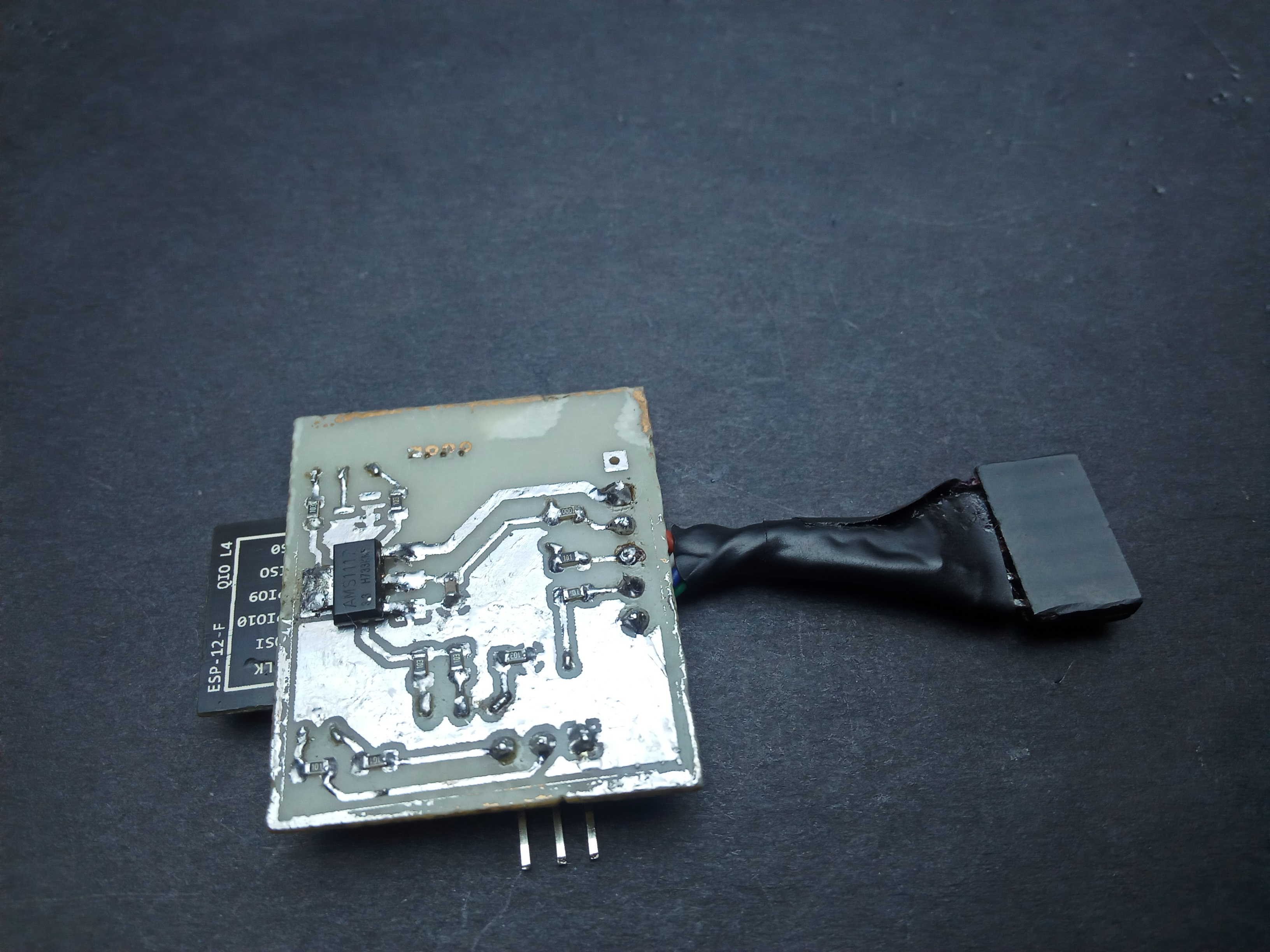
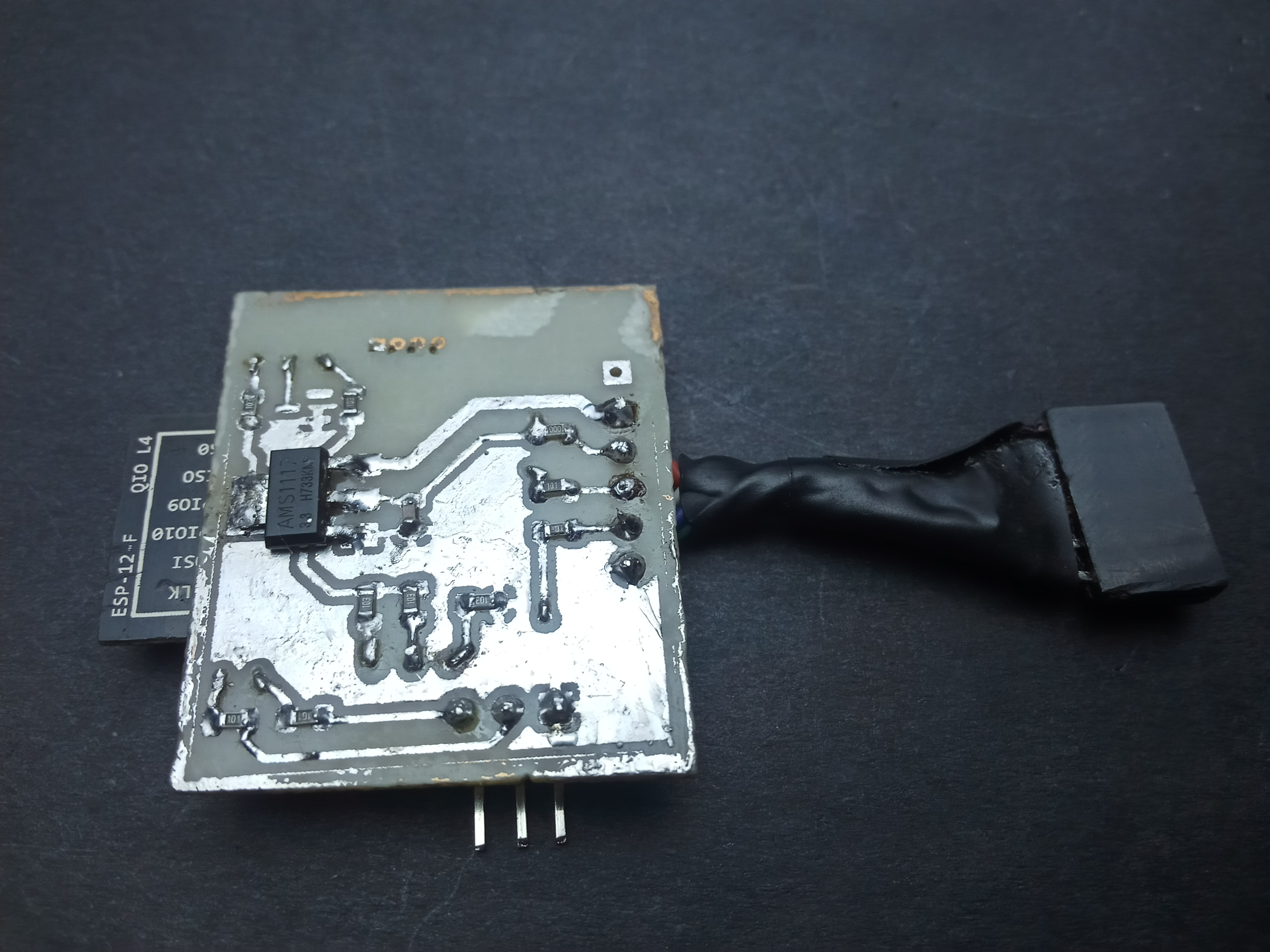
I designed the FishTail as a replacement for an st-link clone. However, failing to account for the orientation of the board, I placed the pins in such a way that connecting to the target board to a jumper soldered directly on the probe would require having the probe upside down. Overcoming this inconvenience necessitated using wires which I ended up twisting into a single heat-shrunk cable with a female jumper at the end: birthing the fishtail.
Features
- Wireless ARM debugging
- Full support for all features of the Blackmagic probe
- Literally foolproof:
- Overvoltage, shorting & reverse polarity protection on pins connected to the target
- On board 1A voltage regulator with upto 12V input
- Open source; completely hackable
Motivation
-
Convenience A wired connection to a target while prototyping on a breadboard adds to the jumbled mess of wires.
-
Flexibility Since the code and schematics are open source, it is possible to modify the device to your liking; from adding features you’d like to designing a custom pcb for a debug port specific to on your target device.
-
Functional security From an STM32 perspective, st-link clones (from China) are a lot more widely available and affordable than a genuine one from ST. That said, you can never really tell the quality of the probe you get. Good ones are based on an STM32F103, just like the one onboard a Nucleo board; however, there are others based on an STM32F101 which lacks the memory resources required to accommodate the latest firmware updates. This means you are stuck with the outdated stock firmware which the STM32Cube IDE just will not work with. Also, I just so happened to blow up the voltage regulator on my st-link clone by reversing the connection on the SWD header; it still works, although I do not get power via USB and rely on the target to power the probe. The FishTail overcomes this ever-looming threat by having over voltage and reverse voltage protection on all of its pins that connect to a target (at present these are the SWD pins and the 3V3 pin only).
Requirements
- NodeMCU (the easiest way to do it: though without any protections on the pins)
OR
- ESP-12F
- USB-UART converter such as CP2102 or CH340
- PCB manufacturing & assembly facilities (Home or Professional)
- A Linux machine to compile the firmware (just my preference, though I might update the tutorial to accomodate Windows users)
- Target board (for testing the probe) – I used an STM32F401 Mini
Also
A big mug of steaming coffee as the process is finicky and will take quite a while.
Procedure
Hardware
The schematics are designed in KiCad 6.0.4 and are available on the FishTail Project repo
A word about the hardware design
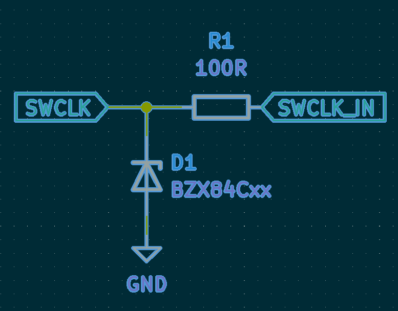
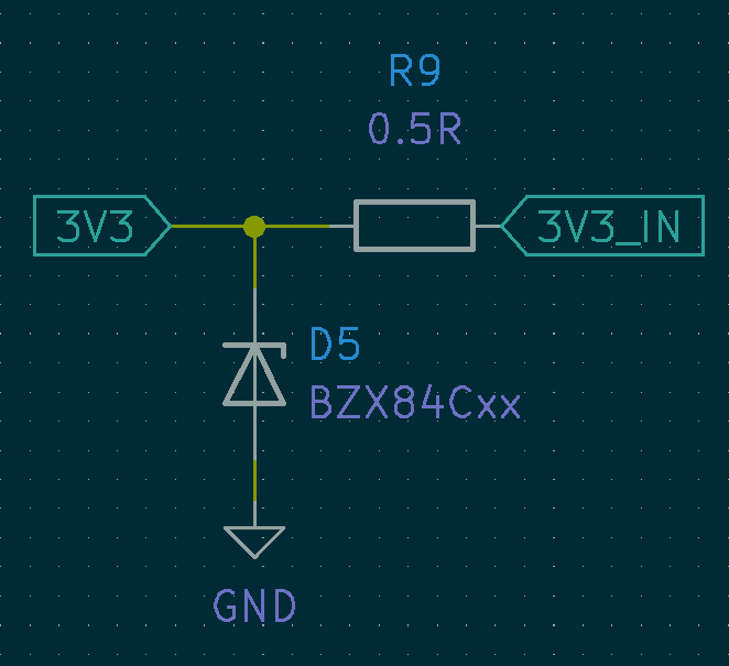
Overvoltage and reverse polarity protection is implemented using a shunt resistor connecting the pin to external circuitry and a 3V3 zener diode between the pin and ground.

- In the event of over voltage, the zener keeps the pin at 3.3V while all the excess voltage is dropped across the shunt resistor R1.

- In the case of reversed polarity, the zener is forward biased creating a closed loop together with R1 that current will flow through rather than flowing through the pin.
Software
FishTail is based on the ESP8266 microcontroller which we need to load with firmware to convert it into a wireless debug probe. The software tools required to achieve this (loosely equivalent to the Arduino IDE for Arduino boards) is the ESP toolchain which we shall set up on a linux machine in this step. The Toolchain Setup section is more or less directly from the official documentation. To do this on Windows or Mac, choose the approprialte guide from the link.
A. Toochain Setup
Prerequisites
Before installing the toolchain, there are prereqiusite packages that must be installed to be able to compile the Toolchain. To do so, run the following command in your terminal:
sudo apt-get install gcc git wget make libncurses-dev flex bison gperf python python-serial
B. Installing the toolchain
-
Download the toolchain for 64-bit Linux https://dl.espressif.com/dl/xtensa-lx106-elf-gcc8_4_0-esp-2020r3-linux-amd64.tar.gz In my case it’s been downloaded into the
~/Downloadsfolder. - Create a new directory named
esp,cdinto it and extract the toolchain here.mkdir -p ~/esp cd ~/esp tar -xzf ~/Downloads/xtensa-lx106-elf-gcc8_4_0-esp-2020r3-linux-amd64.tar.gz - Before it can be used, the toolchain binaries (exexutable files) have to be made accessible from any working directory on the terminal. We do this by adding the following line to the end of your
~/.bashrcfileexport PATH="$PATH:$HOME/esp/xtensa-lx106-elf/bin" - Then
source ~/.bashrcfor the change to take effect
- Run the following command to verify if PATH is correctly set:
echo $PATH | tr ':' '\n' | grep xtensa | uniqand you should get output similar to the following
$: echo $PATH | tr ':' '\n' | grep xtensa |uniq
/home/usr/esp/xtensa-x106-elf/bin
Instead of
/home/usr/there should be a path specific to your installation folder.
Permission issues /dev/ttyUSB0
With some Linux distributions you may get the Failed to open port /dev/ttyUSB0error message when flashing the ESP8266.
If this happens you may need to add your current user to the dialout group which has the appropriate permissions to use serial ports:
sudo usermod -a -G dialout $USER
C. Getting the ESP8266_RTOS_SDK
An SDK (software development kit) is a bunch of pre-written code (libraries) that abstracts away the most basic functionality when programming a microcontroller on which you can build upon your own code. The SDK for the ESP8266 includes a Real-Time Operating System (RTOS).
Clone it from github with the following command:
cd ~/esp
git clone --recursive https://github.com/espressif/ESP8266_RTOS_SDK.git
It takes a while, so you could take a moment to whip up some coffee because we are nearly half way through the build.
As previously established, the ESP8266 development toolchain requires python and python modules to work. From within the ESP8266_RTOS_SDK directory, run the following command to install required python modules.
python -m pip install --user -r requirements.txt
In case you do not have the python package installer installed, run this command before installing the requirements.
curl -sSL https://bootstrap.pypa.io/pip/2.7/get-pip.py -o get-pip.py
if your default python version is python2.7 and
curl -sSL https://bootstrap.pypa.io/get-pip.py -o get-pip.py
for python3, then
python get-pip.py
to install the python package installer, pip.
Finally to install the SDK, run the following commands in the ESP8266_RTOS_SDK
./install.sh
. ./export.sh
and expect the following output if all goes well.
$:  . ./export.sh
Adding ESP-IDF tools to PATH...
Checking if Python packages are up to date...
Python requirements from /home/usr/esp/ESP8266_RTOS_SDK/requirements.txt are satisfied.
Added the following directories to PATH:
  /home/usr/esp/ESP8266_RTOS_SDK/components/esptool_py/esptool
  /home/usr/esp/ESP8266_RTOS_SDK/components/partition_table/
  /home/usr/.espressif/tools/xtensa-lx106-elf/esp-2020r3-49-gd5524c1-8.4.0/xtensa-lx106-elf/bin
  /home/usr/.espressif/python_env/rtos3.4_py2.7_env/bin
  /home/usr/esp/ESP8266_RTOS_SDK/tools
Done! You can now compile ESP8266-RTOS-SDK projects.
Go to the project directory and run:

    make
Building the firmware
Clone the blackmagic-espidf repo and cd into it
git clone --recursive https://github.com/skuodi/fishtail
cd blackmagic-espidf
Then we make changes to the firmware configuration of the probe according to your preference, best done with your terminal window fullscreen
make menuconfig
You should be presented with the following screen:
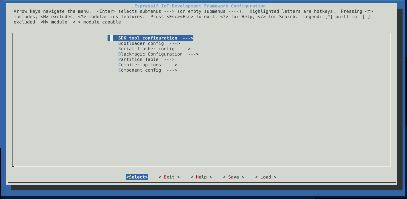
The most important options to us here are Serial flasher config and Blackmagic Configuration
- Under
Serial flasher configyou might need to change the default serial port to the one connected to your FishTail.
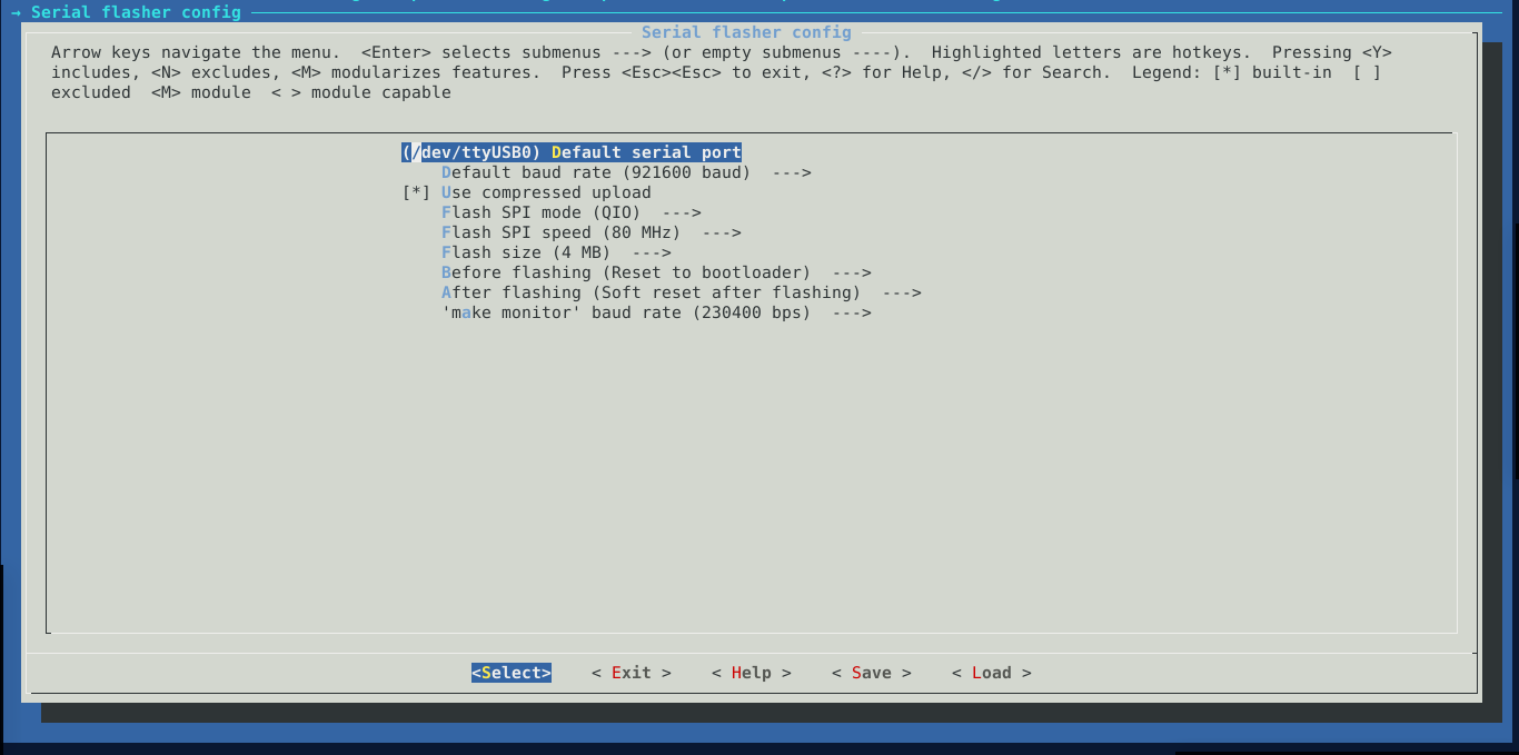
I leave mine as default. Go back to the main menu by pressing the tab key till the Exit option at the bottom is highlighted then pressing enter.
- Next we enter the
Blackmagic Configuration
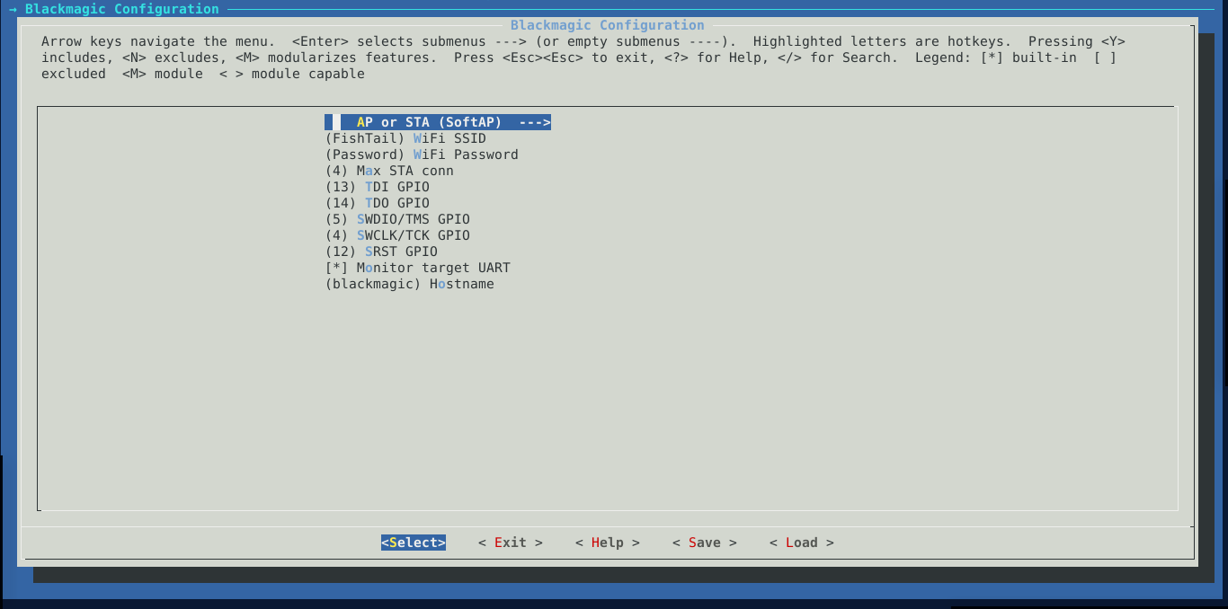
and select the first option.
- If you would like your FishTail to act as a wi-fi access point, use the arrow keys to choose SoftAP and Station if you would rather the probe to connect to an existing wi-fi network (e.g your home network). Next we set the name and password of the wi-fi access point you want the probe to create/connect to.
I chose FishTail for the name, and Password for the password. I strongly recommend you use a more random name and secure password at this point as anyone able to log in to the network will potentially have full control over the target you will be debugging.
- You could also use the fourth option to limit the number of devices allowed to connect to your probe to one so that your computer is the only one connected to the probe while you’re debugging.
- Assign the pins according to your intended use; I was only interested in SWD pins (SWDIO & SWCLK) so I leave the rest as default.
- With the second last option,
- you can choose to use the web-based UART terminal for sending and receiving messages from the target over UART by having the
Monitor target UARToption enabled or - you could disable
Monitor target UARTto allow you to print debug in case when you are working on the firmware for the probe
- you can choose to use the web-based UART terminal for sending and receiving messages from the target over UART by having the
- The last option is much like localhost and should allow you to connect to the probe without having to type out the IP address.
Once you’re done with the settings hit the tab key till
Saveis highlighted and hit enter twice to confirm the save then exit back to the terminal.
Before flashing the firmware to the probe, we need to put it in firmware download mode by closing the solder jumper (labelled SW1) and then power cycling the probe.
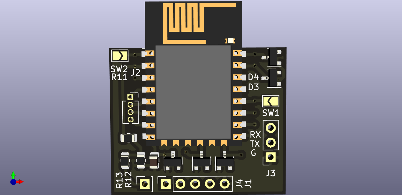
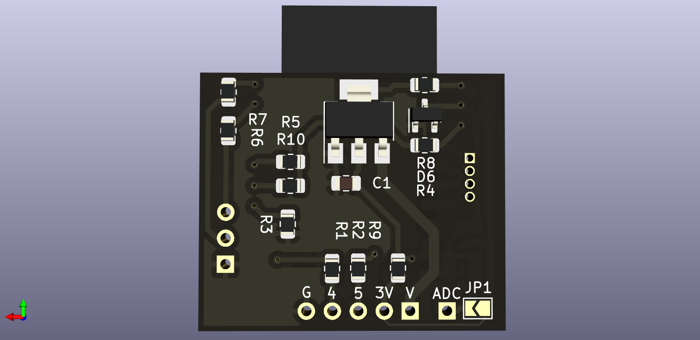
With SW1 closed, connect your USB-UART converter to the probe as follows:
| FishTail | USB-UART converter |
|---|---|
| G | GND |
| TX | RX |
| RX | TX |
| V | 5V |
Now we build the firmware,
make
then flash it to the probe
make flash # this will flash using esptool.py over serial connection
Before having it ready for use, make sure you open the SW1 solder jumper so that the probe boots into run mode when it powers up.
If you have made it this far then congrats! you have your very own wireless debug probe and with very little stretch of the imagination, you can now virtually upload code to an ARM device half way around the world from you!
Project Gallery
Comments